Circuit design verification using checkpointing

a circuit design and checkpoint technology, applied in the field of circuit design verification, can solve the problems of defective circuit design, needing to be re-designed, and the test of circuit design with all possible stimuli would take a long time, and achieve the effect of less tim

Active Publication Date: 2007-12-11
MARVELL ASIA PTE LTD
View PDF10 Cites 2 Cited by
  • Summary
  • Abstract
  • Description
  • Claims
  • Application Information

AI Technical Summary

Problems solved by technology

If a mismatch occurs, the circuit design is considered defective and must be re-designed.
The number of different stimuli may be extremely large and, as a result, testing the circuit design with all possible stimuli would take a very long time.

Method used


Image

  • Circuit design verification using checkpointing
  • Circuit design verification using checkpointing
  • Circuit design verification using checkpointing

Examples


Embodiment Construction

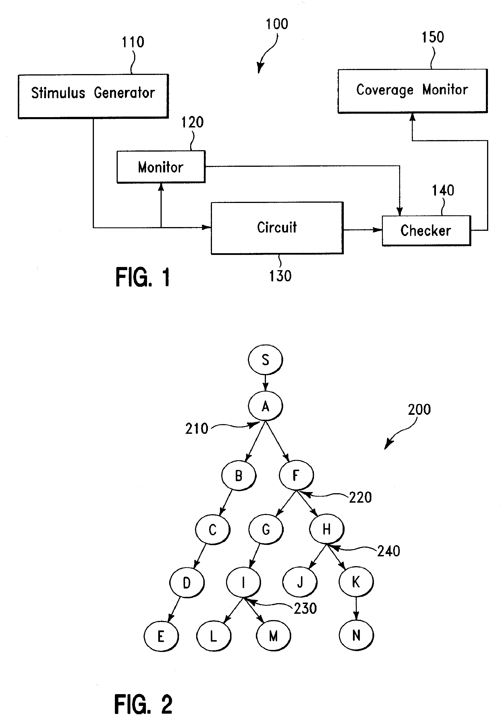
[0018]FIG. 1 illustrates a testing system 100 for verifying (i.e., testing) a circuit 130, in accordance with embodiments of the present invention. More specifically, in one embodiment, the verification of the circuit 130 proceeds as follows. A stimulus generator 110 generates a stimulus to the circuit 130 and to a monitor 120. The circuit 130 receives as input the stimulus from the stimulus generator 110 and generates an output signal to a checker 140. The monitor 120 records the stimulus given to the circuit 130. In one embodiment, the monitor 120 converts the stimulus into a useful form before sending it to the checker 140. The checker 140 calculates an expected result from the information provided by the monitor 120 and compares the output signal from the circuit 130 and the calculated expected result. Any difference between the output signal from the circuit 130 and the calculated expected result indicates a potential error in the circuit 130.

[0019]In one embodiment, the checke...


PUM


Abstract

A design verification method, comprising providing a circuit design; creating a stimulus tree diagram for the circuit design, wherein the stimulus tree diagram comprises L stimuli, M checkpointed splits, and N non-checkpointed splits; and executing the stimulus tree diagram, wherein said executing the stimulus tree diagram comprises, for i=1, . . . , M, executing an ith checkpointed split of the M checkpointed splits, wherein said executing the ith checkpointed split comprises (a) saving an ith context of an ith simulation environment in which said executing the stimulus tree diagram is performed; and (b) after said saving the ith context is performed, executing from the ith context along Pi paths of the stimulus tree diagram branching from the ith checkpointed split, wherein the ith checkpointed split is a Pi-way split, Pi being an integer greater than 1.

Description

BACKGROUND OF THE INVENTION[0001]1. Technical Field[0002]The present invention relates to circuit design verification, and more specifically, to circuit design verification using checkpointing.[0003]2. Related Art[0004]A circuit design after being created is usually verified (i.e., tested) before being actually fabricated. Typically, the circuit design is verified by running a simulation program on a computer (not shown) during which different inputs (called stimuli) are in turn applied to the circuit design and the signals at the outputs and different nodes of the circuit design are collected and compared with expected values. If a mismatch occurs, the circuit design is considered defective and must be re-designed. The number of different stimuli may be extremely large and, as a result, testing the circuit design with all possible stimuli would take a very long time. Therefore, there is a need for a method for verifying the circuit design in relatively less time than in the prior a...

Claims


Application Information

Patent Timeline
Patent Type & Authority Patents(United States)
IPC IPC(8): G06F17/50G06G7/62
CPCG06F17/5022G06F30/33
Inventor CRAIG, JESSE E.NORMAN, JASON M.
Owner MARVELL ASIA PTE LTD
Why Eureka
Try Eureka