
Ear temperature monitor and method of temperature measurement

Inactive Publication Date: 2007-12-11
ADVANCED MONITORS
View PDF146 Cites 19 Cited by
  • Summary
  • Abstract
  • Description
  • Claims
  • Application Information

AI Technical Summary

Benefits of technology

[0012]The goals of this invention is achieved by the novel ear temperature detector. The detector is comprised of an ear plug carrying the temperature sensing device wherein the sensing device is characterized by its increased thermal coupling to a wall of an ear canal and decreased coupling to the environment. This is attained by pre-shaping the plug into a smaller size and allowing to change its shape upon the insertion, until the

Problems solved by technology

The last device presently can not provide a continuous monitoring.
These traditional devices are invasive, may require sterile probes (esophageal), often inconvenient and, as a rule, not acceptable for patients outside the operating rooms.
Generally, this can be performed only on an anesthetized patient with a risk of damaging the tympanic membrane and thus is rarely used in medical practice.
Contact detectors are much simpler than noncontact, but they both suffer from the same effect—difficulty of a reliable placement inside the ear canal.
Placement of a contact temperature transducer inside the ear canal without a reliable securing of it at any specific position may cause a high inaccuracy in measurement, due to unpredictable effects of the ambient temperature and placement technique of the probe.
Yet, the teaching does not resolve the accuracy problem due to heat loss.
Besides, such a probe requires an individual tailoring of its shape.

Method used


Image

  • Ear temperature monitor and method of temperature measurement
  • Ear temperature monitor and method of temperature measurement
  • Ear temperature monitor and method of temperature measurement

Examples


Embodiment Construction

[0026]The present invention describes a device and method for obtaining information from a body cavity. At least three essential elements are required for this invention to work: a temperature transducer, a thermal insulator, and an external temperature sensor.

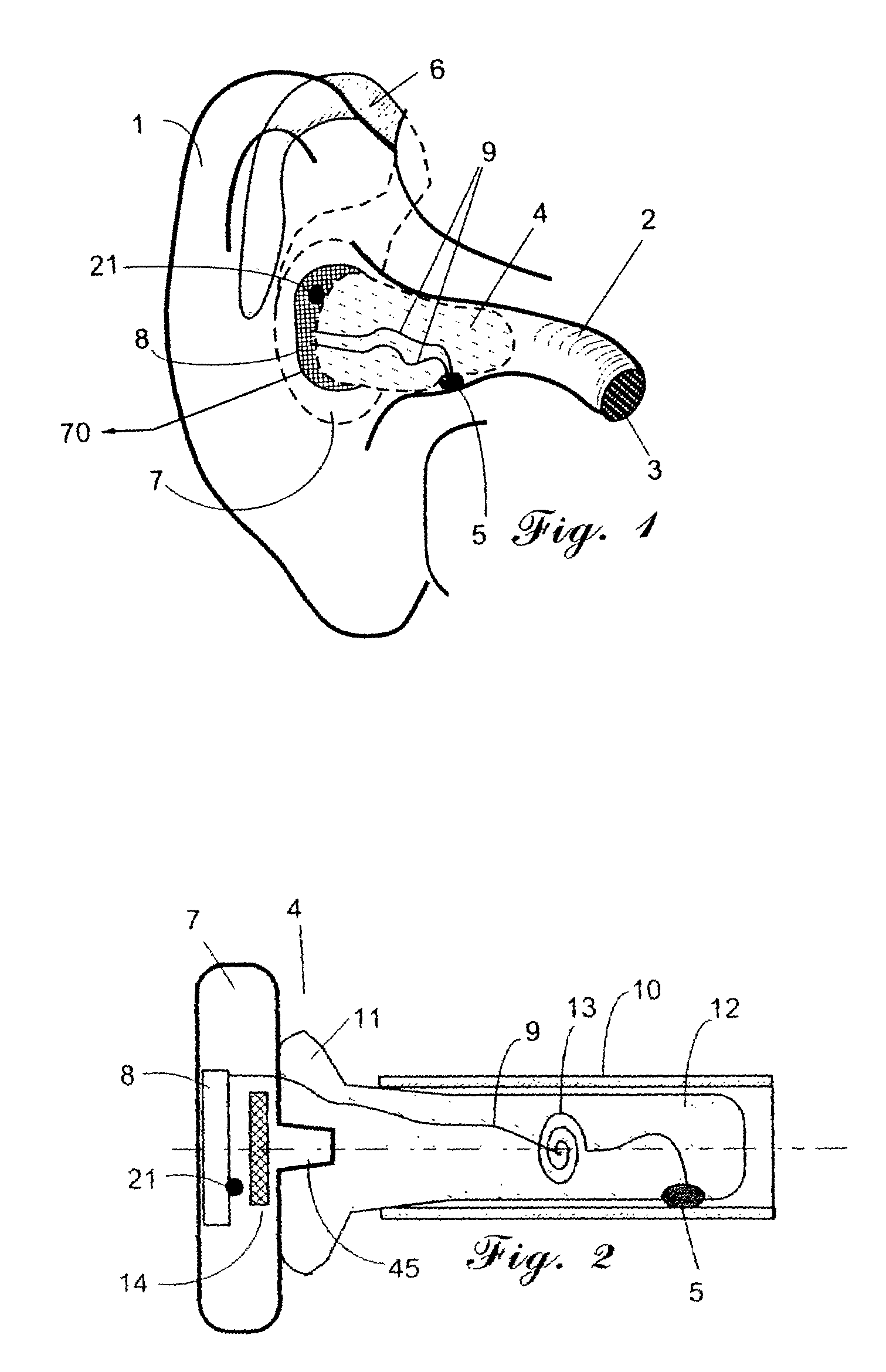
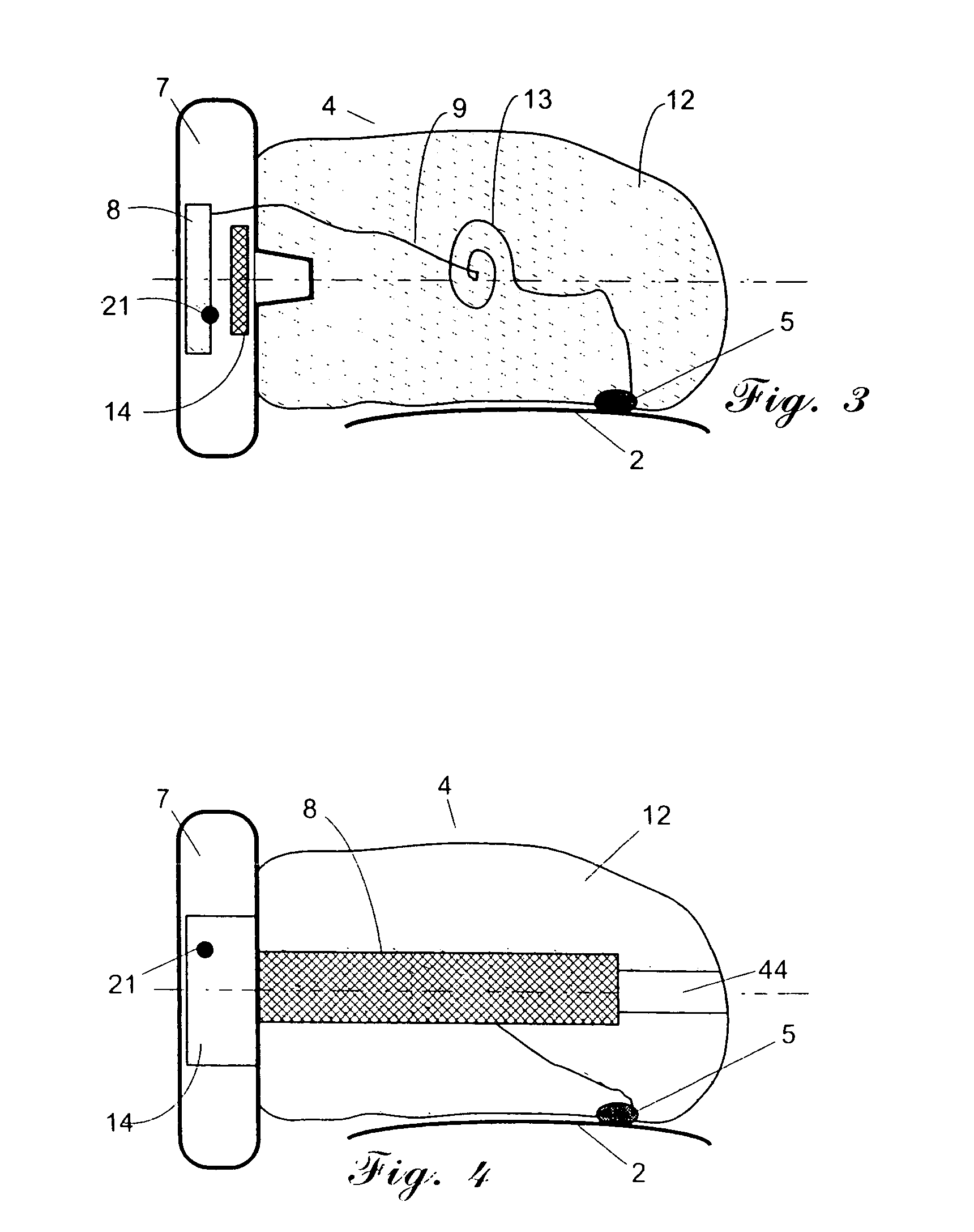
[0027]A preferred embodiment is illustrated herewith by showing how this can be accomplished with improved accuracy when the information is temperature and the body cavity is an ear canal of a human or other animal. The major task for accomplishing the stated goals is to increase a thermal coupling between the ear canal walls and a temperature transducer, while minimizing such coupling to the external environment. FIG. 1 illustrates an ear plug 4 that is inserted into ear 1, but not reaching the tympanic membrane 3. Temperature transducer 5 is clamped between plug 4 and ear canal walls 2. The transducer is connected to the electronic module 8 via wires 9. There may be more than one transducer attached to the plug, but for the ...


PUM


Abstract

A continuous body core temperature monitor comprises a pliable ear plug that conforms to the shape of an ear canal and incorporates a temperature sensor that is clamped between the plug and the ear canal wall. The external surface of the plug is connected to an external temperature sensor and a heating element that compensate for a heat lost from the ear canal to the environment by maintaining the temperature gradient between the temperature sensor and the heating element close to zero.

Description

[0001]This application is a continuation of application Ser. No. 09 / 927,179, filed on Aug. 8, 2001 (now U.S. Pat. No. 6,773,405), which claims the benefit of U.S. provisional application Ser. No. 60 / 233,104, filed on Sep. 15, 2000 (abandoned), the disclosures of which are fully incorporated herein by reference.FIELD OF THE INVENTION[0002]This invention relates to a method of monitoring temperature of a human body and devices for achieving same and, more particularly, to such a method and device which monitors the internal core temperature of a person undergoing continuous medical observation.DESCRIPTION OF PRIOR ART[0003]Frequently, during surgical and other medical procedures related to humans and animals, there is a need for continuous monitoring of the body core temperature. Core temperature here means temperature of blood flowing around the brain and other vital internal organs. It has been recognized long time ago that the core temperature is an accurate parameter for assessing...

Claims


Application Information

Patent Timeline
IPC IPC(8): A61B5/00A61B5/01G01K13/00G01K13/02
CPCA61B5/01G01K13/022G01K1/165G01K13/002A61B5/6817A61B5/0002A01K29/005G01K13/20
Inventor FRADEN, JACOBFERLITO, RICHARD K.
Owner ADVANCED MONITORS
Learn More