
Mask-programmable logic device with programmable input/output ports

a programmable logic and input/output port technology, applied in the field of mask-programmable logic devices, can solve the problems of increasing the size and power consumption of such devices, not being able to route the user design with the available routing resources, and particular mask-programmable logic devices, like conventional programmable logic devices, can only accommodate a certain size of user logic designs, etc., to achieve convenient parallel connection, reduce blockages, and increase routability

Inactive Publication Date: 2007-12-04
ALTERA CORP
View PDF5 Cites 2 Cited by
  • Summary
  • Abstract
  • Description
  • Claims
  • Application Information

AI Technical Summary

Benefits of technology

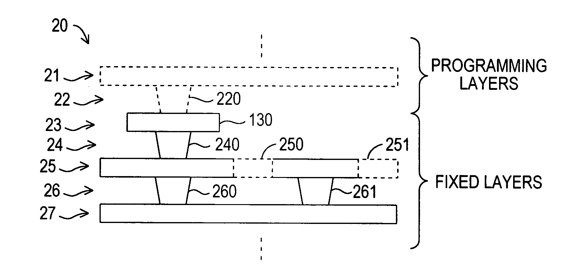
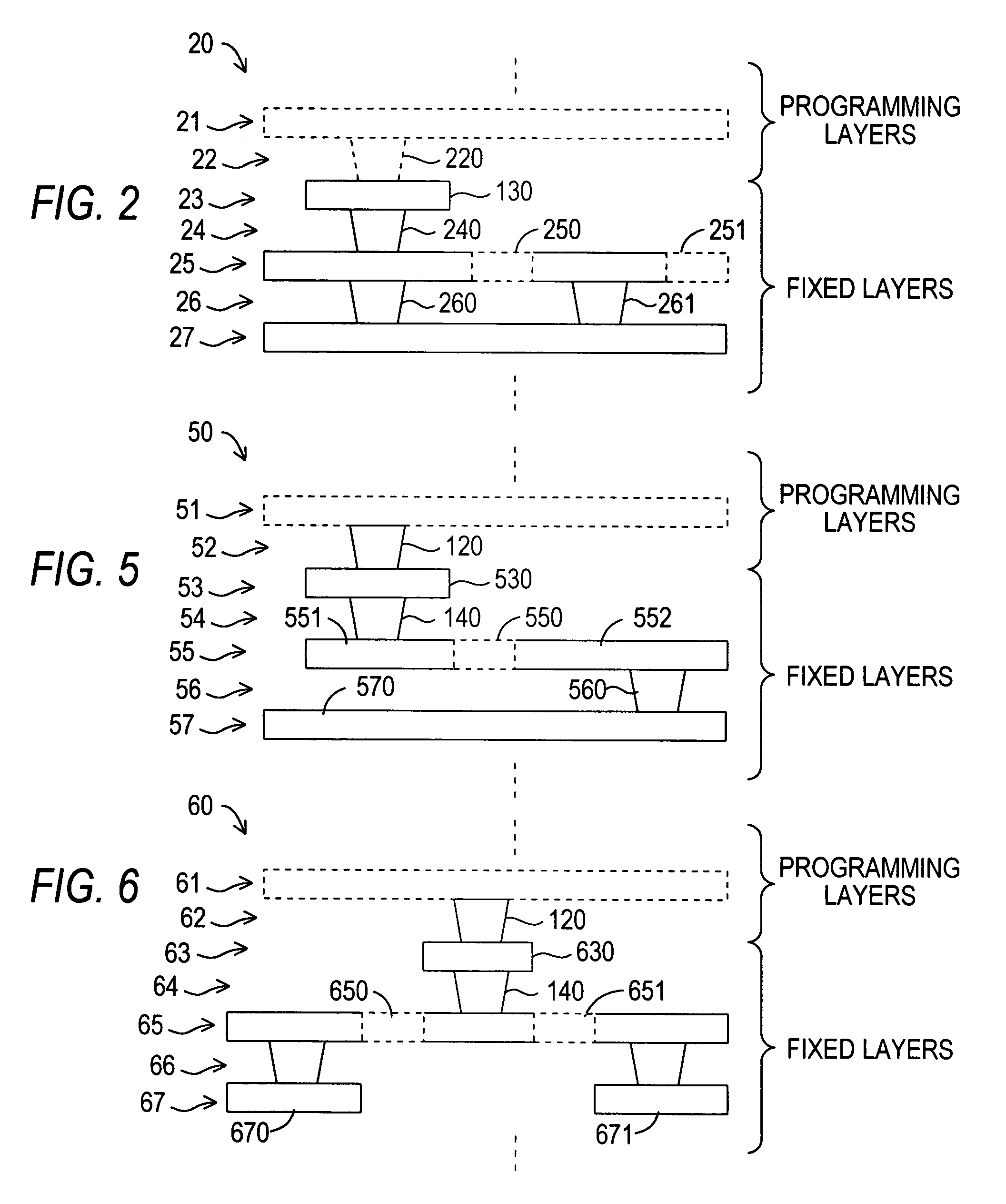
[0014]In accordance with the invention, the ports (both internal and external) are arranged so that, depending on how the programmable layer is programmed, the external port can be isolated. This allows the external port to become a floating port, so that an unused port does not create a routing blockage. Also, the ports are arranged so that more than one internal port can be connected to the external port. This allows several different internal ports to share a single external port. The ability of more than one internal port to be connected to a single external port increases routability (reduces blockages), and also facilitates parallel connection of two groups of logic circuitry to the external port in those cases where that is desired. Another possibility is that two logic circuits that share an external port can communicate with one another via the shared port, without requiring routing via the programming metallization layers.

Problems solved by technology

While conventional programmable logic devices allow a user to easily design a device to perform a desired function, a conventional programmable logic device invariably includes resources that may not be used for a particular design.
Moreover, in order to accommodate general purpose routing and interconnect resources, and the switching resources that allow signals from any logic element to reach any desired routing and interconnect resource, conventional programmable logic devices grow ever larger as more functionality is built into them, increasing the size and power consumption of such devices.
It is axiomatic that a particular mask-programmable logic device, like a conventional programmable logic device, can only accommodate a user logic design of a certain size.
However, in most cases, when the limit of the size of the user logic design is reached, it is reached because all of a particular type of resource—either a routing or logic resource—has been used, even though there may other types of resources on the device that remain unused.
For example, it may not be possible to route the user design with the available routing resources, while at the same time some of the aforementioned I / O ports remain unused.

Method used


Image

  • Mask-programmable logic device with programmable input/output ports
  • Mask-programmable logic device with programmable input/output ports
  • Mask-programmable logic device with programmable input/output ports

Examples


first embodiment

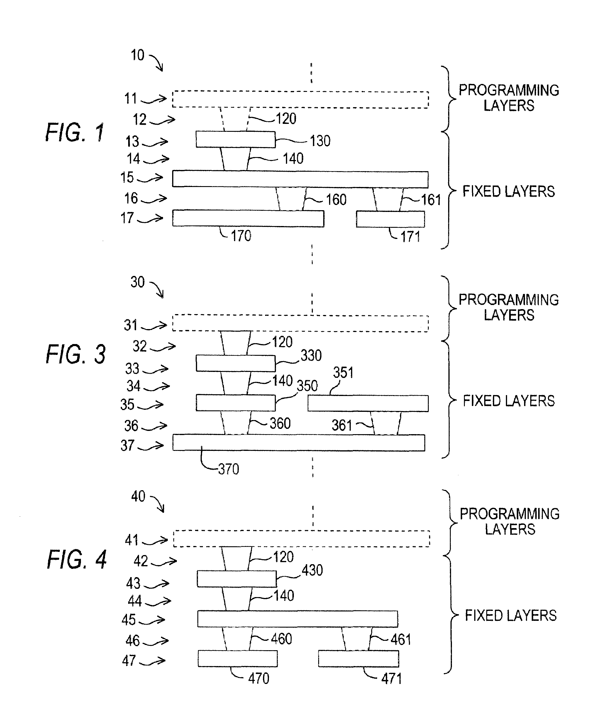
[0030]FIG. 3 shows a mask-programmable logic device 30 in accordance with the present invention. In this embodiment, as compared to FIG. 1, structures 170, 171 in bottom layer 17 of device 10 have been replaced by structures 350, 351 in layer 35, just below external port 330 (separated therefrom by semiconductor layer 34). Only one of structures 350, 351 is connected to external port 330, while both are connectable by programmable vias 360, 361 to internal port 370. In this embodiment, if it desired to isolate external port 330, that can be accomplished by not programming via 360 to conduct.

second embodiment

[0031]a mask-programmable logic device 40 in accordance with the present invention, shown in FIG. 4, is similar to FIG. 1. Structures 170, 171 in bottom layer 17 of device 10 have been replaced by structures 470, 471 in layer 47, and may serve as internal ports for logic circuitry provided elsewhere in those layers or in layers that are not shown. Internal ports 470, 471 may share external port 430 through metal layer 45, by programming appropriate one of vias 460, 461 to conduct, so that the desired one, or both, of internal ports 470, 471 is connected to external port 430. Also, in this embodiment, external port 430 may be isolated by programming both of vias 460, 461 not to conduct.

[0032]Because in embodiments 30 and 40 the external port can be isolated without regard to the programming layers, layer 32, 42 can be made fixed, rather than programmable like layers 12 and 22. Only layer 31, 41 (and possibly other layers not shown) may be programmable. This can represent a cost savin...


PUM


Abstract

A mask-programmable logic device includes a macrocell having an external input / output port for “place-and-route” programming by addition of metallization layers. A programmable “fixed” layer allows the external input / output port to be isolated from the remainder of the macrocell so that it “floats,” allowing signals to be routed through the external input / output port when the macrocell is not in use, to reduce routing blockages. The macrocell also may have at least one internal input / output port, potentially connected to different logic circuits, and a programmable “fixed” layer that can be used to control which internal input / output port is connected to the external input / output port. By thus allowing multiple logic circuits to share a single external input / output port, routing blockages are reduced.

Description

BACKGROUND OF THE INVENTION[0001]This invention relates to mask-programmable logic devices having both fixed and programmable layers, where the input / output (“I / O”) ports are located in the fixed layers but are programmable.[0002]Programmable logic devices are well known. Early programmable logic devices were one-time configurable. For example, configuration may have been achieved by “blowing”—i.e., opening—fusible links. Alternatively, the configuration may have been stored in a programmable read-only memory. These devices generally provided the user with the ability to configure the devices for “sum-of-products” (or “P-TERM”) logic operations. Later, such programmable logic devices incorporating erasable programmable read-only memory (EPROM) for configuration became available, allowing the devices to be reconfigured.[0003]Still later, programmable logic devices incorporating static random access memory (SRAM) elements for configuration became available. These devices, which also c...

Claims


Application Information

Patent Timeline
Patent Type & Authority Patents(United States)
IPC IPC(8): H03K19/173H03K19/00
CPCH03K19/17744H03K19/17796H03K19/17748
Inventor PHOON, HEE KONGYAP, KIAN CHIN
Owner ALTERA CORP
Learn More