Dynamic membrane wafer assembly and method
a technology of dynamic membrane wafers and membrane wafers, applied in the direction of membranes, separation processes, filtration separation, etc., can solve the problems of high cost of prior art spiral-wound elements, difficult high temperature service production, and high cost of interconnection of these equipment devices for large flow rate applications, so as to enhance the overall pervaporation of fluids, compact equipment size, and high integration
- Summary
- Abstract
- Description
- Claims
- Application Information
AI Technical Summary
Benefits of technology
Problems solved by technology
Method used
Image
Examples
second embodiment
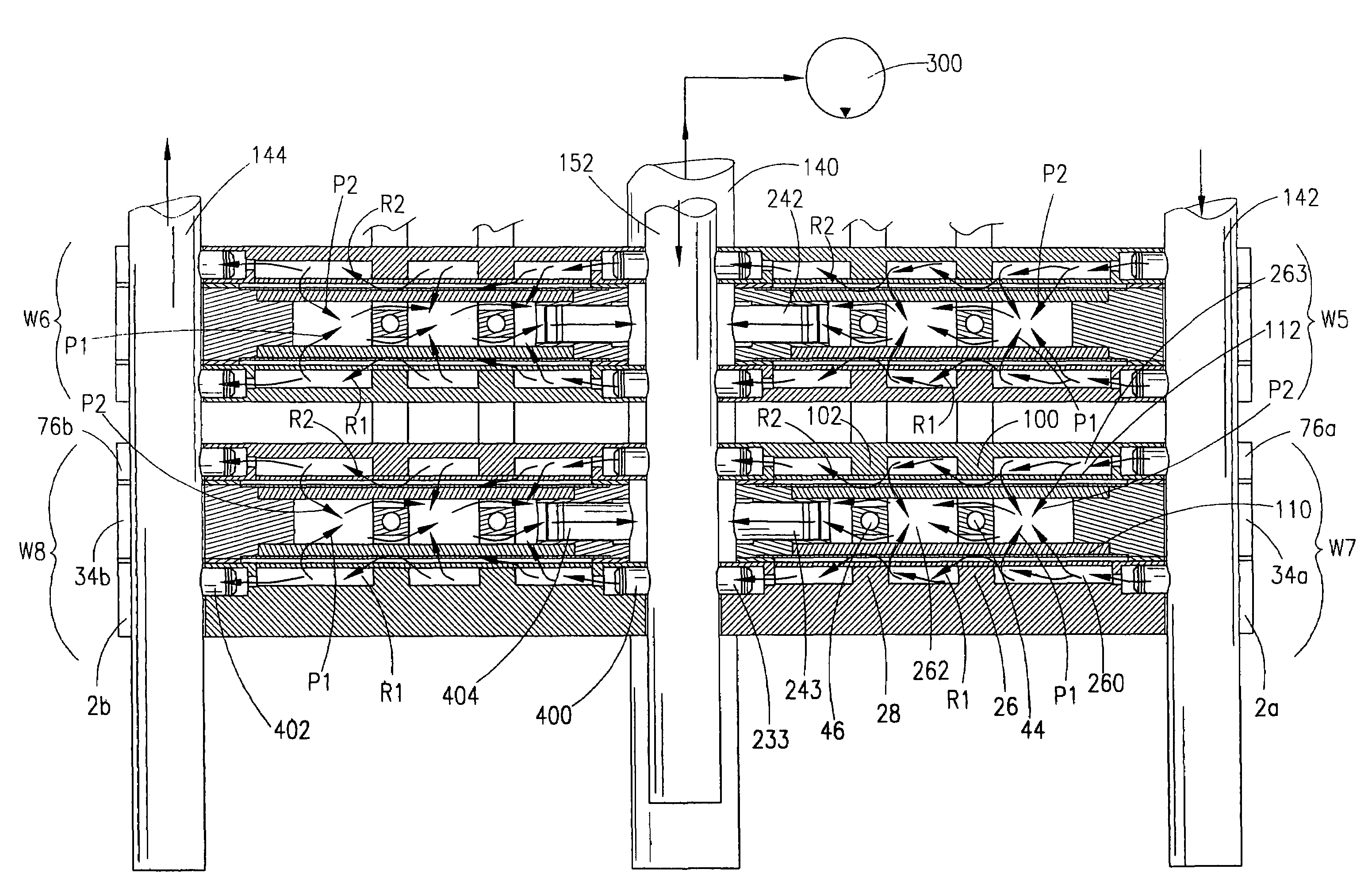
[0075]FIG. 5B is an exploded side elevation view of the tandem wafer assemblies seen in FIG. 4 detailing the membrane member package. The embodiment of FIG. 5B depicts the dynamic membrane. In this second preferred embodiment, the membrane member 400 comprises O-ring rope 409a, a wire mesh screen 410a, a powdered layer of adsorption media 412a, membrane 414a, membrane support fabric 416a, and O-ring rope 417a. Also included is a porous support material media 418a, which may be either a porous metallic or porous ceramic support material abutting the membrane support fabric.
[0076]Conventional O-ring rope can be used; O-ring rope available from American Seal Inc. under the name Cabres is suitable. The feed spacer screen (410a) can be conventional metal or non-metallic screen materials. Conventional membrane support fabric can be used, such as a Teflon polyetrafluoroethylene (PTFE) fabric (GoreTex), available from W. L. Gore, Inc. The membrane support fabric may also be polyester, nylon...
first embodiment
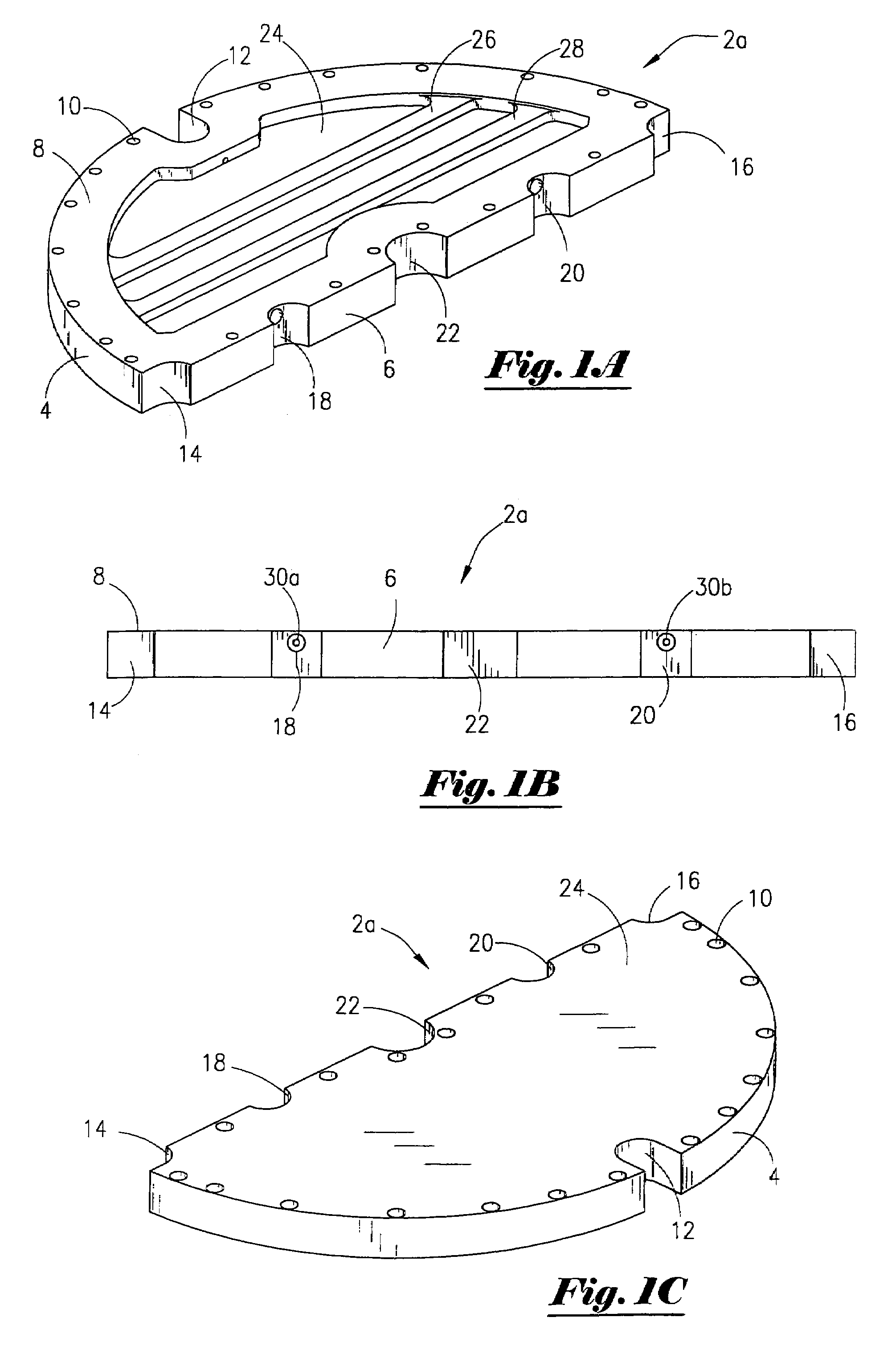
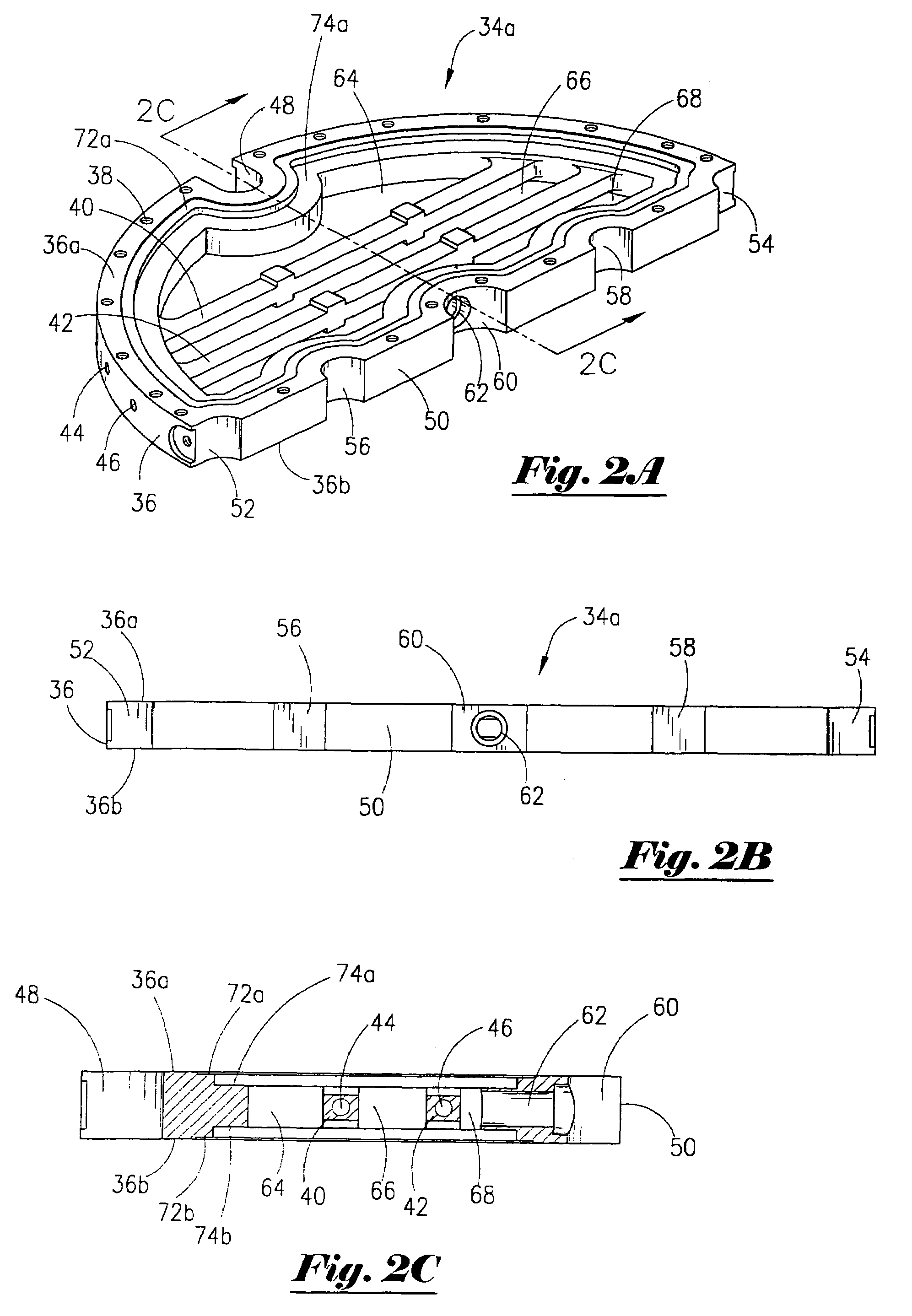
[0097]In FIG. 11A, a seal member for the wafer assembly will now be described. The seal member shown in FIG. 11A is a gasket 270 that is well known in the art. The wafer 2a contains a rim 272 on its perimeter, and the internal wafer 34a contains a reciprocal rim 274 on its perimeter. A screen 276 (which for example may be a component of the membrane member package 110 or of membrane member package 400) is shown configured to be positioned within a ledge surface 277a of the wafer 34a. The thin film membrane is denoted by the numeral 278. Therefore, the gasket 270 is placed between the rims 272 and 274 in order to provide a seal means. The gasket 270 can be Viton, or another elastomer suitable for service with the desired feedstream, permeate, retentate, and process conditions.
[0098]A second embodiment of a seal member for the wafer assembly is shown in FIG. 11B. In this embodiment, the screen 276 is used with the membrane member denoted by the numeral 280. The gasket 270 is again use...
third embodiment
[0099]In FIG. 11C, a seal member for the wafer assembly is shown. In this embodiment, the O-ring 284 is again positioned within the ledge 282. In the wafer 2a, two grooves are configured in rim 272, namely, groove 286 and groove 288. An O-ring 290 is placed within groove 286 and an O-ring 292 is within groove 288. This embodiment allows the O-ring 290 and the O-ring 284 to cooperate together for a sealing means. The O-ring 292 provides a redundant seal, with the seal occurring between the O-ring 292 and the membrane member 280.
[0100]The membranes described herein are useful for separating a desired component or species from a liquid feed. Perstractive and pervaporative separation can be used.
[0101]In perstractive separation, permeate is removed from the permeate zone using a liquid sweep stream. The permeate dissolves into the sweep stream and is conducted away by sweep stream flow in order to prevent the accumulation of permeate in the permeate zone. The sweep liquid preferably has...
PUM
| Property | Measurement | Unit |
|---|---|---|
| temperatures | aaaaa | aaaaa |
| temperature | aaaaa | aaaaa |
| temperature | aaaaa | aaaaa |
Abstract
Description
Claims
Application Information
 - R&D
- Intellectual Property
- Life Sciences
- Materials
- Tech Scout
- Unparalleled Data Quality
- Higher Quality Content
- 60% Fewer Hallucinations
Browse by: Latest US Patents, China's latest patents, Technical Efficacy Thesaurus, Application Domain, Technology Topic, Popular Technical Reports.
© 2025 PatSnap. All rights reserved.Legal|Privacy policy|Modern Slavery Act Transparency Statement|Sitemap|About US| Contact US: help@patsnap.com


