
Mounting system and method for rigidly attaching a water sports towing frame to a vessel

a technology for mounting systems and water sports towing equipment, which is applied in the field of mounting brackets, can solve the problems of installation inefficiency and inaccuracy, installation to have to drill holes, and difficulty in accurately and efficiently mounting the frame to the boat deck

Inactive Publication Date: 2007-12-04
CORRECT CRAFT IP HLDG
View PDF19 Cites 26 Cited by
  • Summary
  • Abstract
  • Description
  • Claims
  • Application Information

AI Technical Summary

Benefits of technology

"The present invention is a mounting system for securely attaching a water sports towing frame to a vessel. The system includes a towing frame with a leg, a support structure with an aperture, and a joint member with a cavity and a threaded bore. A shaft is extended through the aperture of the support structure and the joint member, and a fastener is used to secure the joint member to the support structure. The system also includes a base with an aperture and a rotatable spherical joint, which can be secured to a threaded rod. The towing frame is pre-attached to the spherical joint, and the assembly is secured to the deck of the boat using the threaded rod and a nut. The technical effect of the invention is a secure and adjustable mounting system for water sports towing frames to a vessel."

Problems solved by technology

As is well known in the art, accurately and efficiently mounting the frame to the boat deck is often complicated by an out of plane deck top surface, imprecise mounting plate dimensions and features, generally unexpected appendages, and the like.
However, whether pivotally mounting or fixed, the unevenness of most decks presents installation inefficiencies and inaccuracies that may include misaligning the frame.
By way of example, if the mounting plate has four bolts aligning the bolts within four holes passing through the deck while accounting for unevenness of the deck may cause the installer to have to re-drill holes which for those skilled in the art will appreciate is not a desirable method of installation.

Method used


Image

  • Mounting system and method for rigidly attaching a water sports towing frame to a vessel
  • Mounting system and method for rigidly attaching a water sports towing frame to a vessel
  • Mounting system and method for rigidly attaching a water sports towing frame to a vessel

Examples


Embodiment Construction

[0024]The present invention will now be described more fully hereinafter with reference to the accompanying drawings, in which preferred embodiments of the invention are shown. This invention may, however, be embodied in many different forms and should not be construed as limited to the embodiments set forth herein. Rather, these embodiments are provided so that this disclosure will be thorough and complete, and will fully convey the scope of the invention to those skilled in the art. Like numbers refer to like elements throughout, and prime notation is used to indicate similar elements in alternate embodiments.

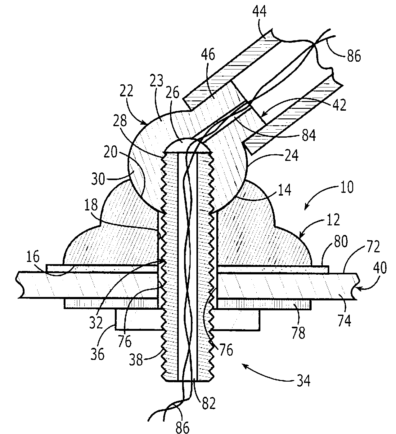
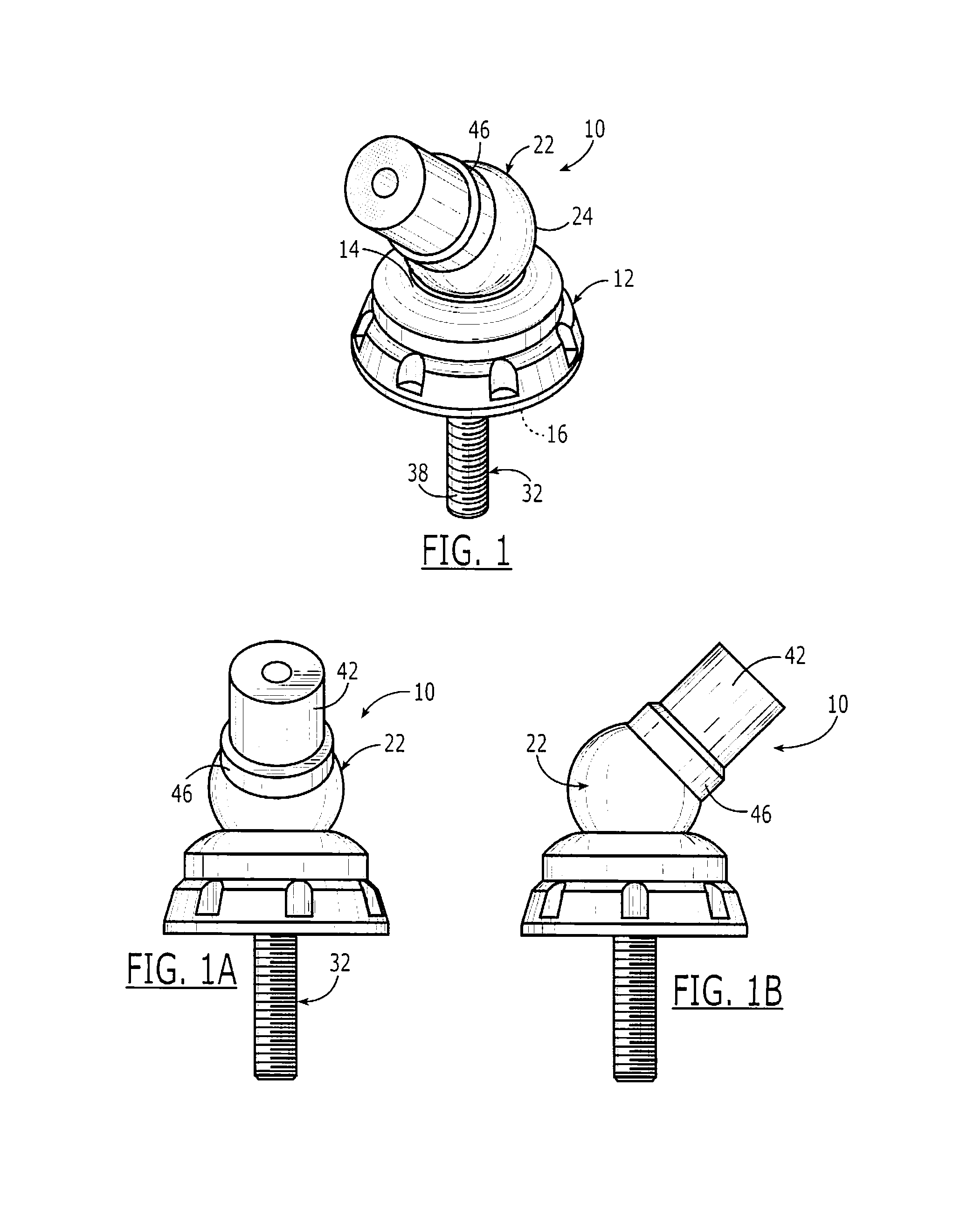
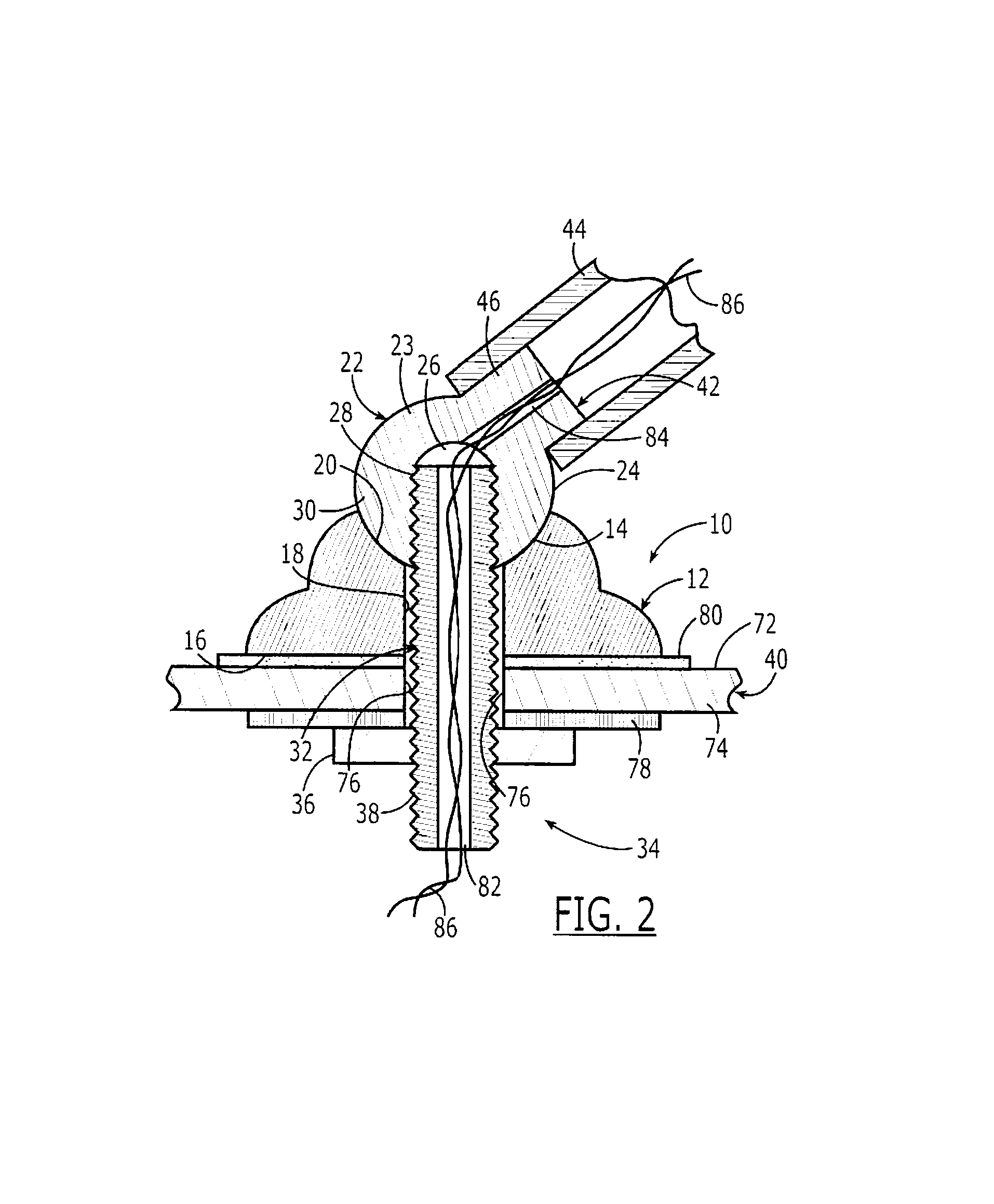
[0025]Referring initially to FIG. 1, one mounting bracket 10 in keeping with the teachings of the present invention comprises a base 12 herein defined as having a top surface 14 and an opposing bottom surface 16. As illustrated with reference to FIG. 2, a bore 18 extends through the base 12. The top surface 14 includes an arcuate surface portion 20, herein concave, by way of ...


PUM


Abstract

A mounting system rigidly attaches a towing frame to a vessel deck, and includes a base having an arcuate top surface and a bottom surface conforming the deck. A joint member rigidly attached to the towing frame has an arcuate surface mating with the arcuate top surface of the base. The joint member has a cavity and a threaded bore extending through a wall for accessing the cavity. The threaded bore of the joint member is aligned with a bore extending through the base. A threaded shaft extends through a hole in the deck, through the bore in the base, and is threaded into the threaded bore of the joint member. A fastener attached to the shaft is used to bias the joint member against the base, and base against the deck for rigidly securing the joint member and thus the towing frame to the deck.

Description

CROSS-REFERENCE TO RELATED APPLICATIONS[0001]This application claims the benefit of U.S. Provisional Application No. 60 / 702,122, filed Jul. 25, 2005, for “Water Sports Towing Apparatus Mounting Device and Method,” the disclosure of which is hereby incorporated by reference herein in its entirety, and commonly owned.FIELD OF THE INVENTION[0002]The present invention relates to mounting brackets and in particular to a mounting system and method for a water sports towing apparatus.BACKGROUND OF THE INVENTION[0003]As described by way of example with reference to U.S. Pat. No. 6,666,159 for a “Water Sport Towing Apparatus,” it is well known to mount skeletal frames to boat decks. Typically, extremities of leg portions of a skeletal structure are mounted to deck portions of a boat using a mounting plate placed on a top surface of the deck, a backing plate positioned on an opposing bottom surface, and a fastening together using a nut and bolt arrangement. Legs of the skeletal structure may ...

Claims


Application Information

Patent Timeline
Patent Type & Authority Patents(United States)
IPC IPC(8): B63B17/00
CPCB63B34/60
Inventor CARLTON, STEPHEN
Owner CORRECT CRAFT IP HLDG
Learn More