
Hazard countermeasure system and method for vehicles

a technology for countermeasure systems and vehicles, applied in the field of vehicle control systems, can solve problems such as visibility hazards, transient visibility hazards, and endanger vehicles within, and achieve the effect of reducing the risk of both long-term and transient hazards and reducing the risk of visibility hazards

Inactive Publication Date: 2007-11-27
GRAY JUSTIN
View PDF6 Cites 31 Cited by
  • Summary
  • Abstract
  • Description
  • Claims
  • Application Information

AI Technical Summary

Benefits of technology

"The invention is a system that helps vehicles mitigate both long-term and transient hazards. It uses data from a vehicle position determining system, a geographic database of potential hazards, and external data networks to automatically activate vehicle systems that provide countermeasures to hazards. The system can also communicate with external facilities like 911 or a police station to alert them about the hazard. The system can also post information about hazards to external data networks, allowing others to see the risk and take appropriate action. Overall, the system helps drivers and passengers stay safe by automatically activating the appropriate vehicle control systems in response to potential hazards."

Problems solved by technology

An event such as an armed robbery, a burglary, a carjacking or other similar crime presents a hazard to occupants of a vehicle approaching the proximity of the event.
A transient condition, such as fog, smoke, dust, precipitation or other suspended particles presents, a hazard to a vehicle approaching and entering it by obscuring obstacles within it.
A transient visibility hazard also endangers vehicles within and obscured by it that may be moving at a slower speed than vehicles on the same path behind them.
An accident, sudden delays in traffic and other situations may also cause a visibility hazard by diverting vehicle operators' attention.
Rapid changes in temperature or humidity may also cause a visibility hazard by causing condensation to form on windows.
Low levels of ambient light can also cause a visibility hazard to inattentive vehicle operators.
A transient condition, such as smoke, dust or other suspended particles, presents a hazard to occupants of a vehicle approaching and entering it by inhalation.
A collision between vehicles, a vehicle fire, a damaged hazardous-material-bearing vehicle, a stationary fire or a polluting factory may all release hazardous or unpleasant fumes, particles or gases.

Method used


Image

  • Hazard countermeasure system and method for vehicles
  • Hazard countermeasure system and method for vehicles
  • Hazard countermeasure system and method for vehicles

Examples


Embodiment Construction

[0025]The following detailed description of the preferred embodiment of this invention and the attached figures are intended to provide a clear description of the invention without limiting its scope.

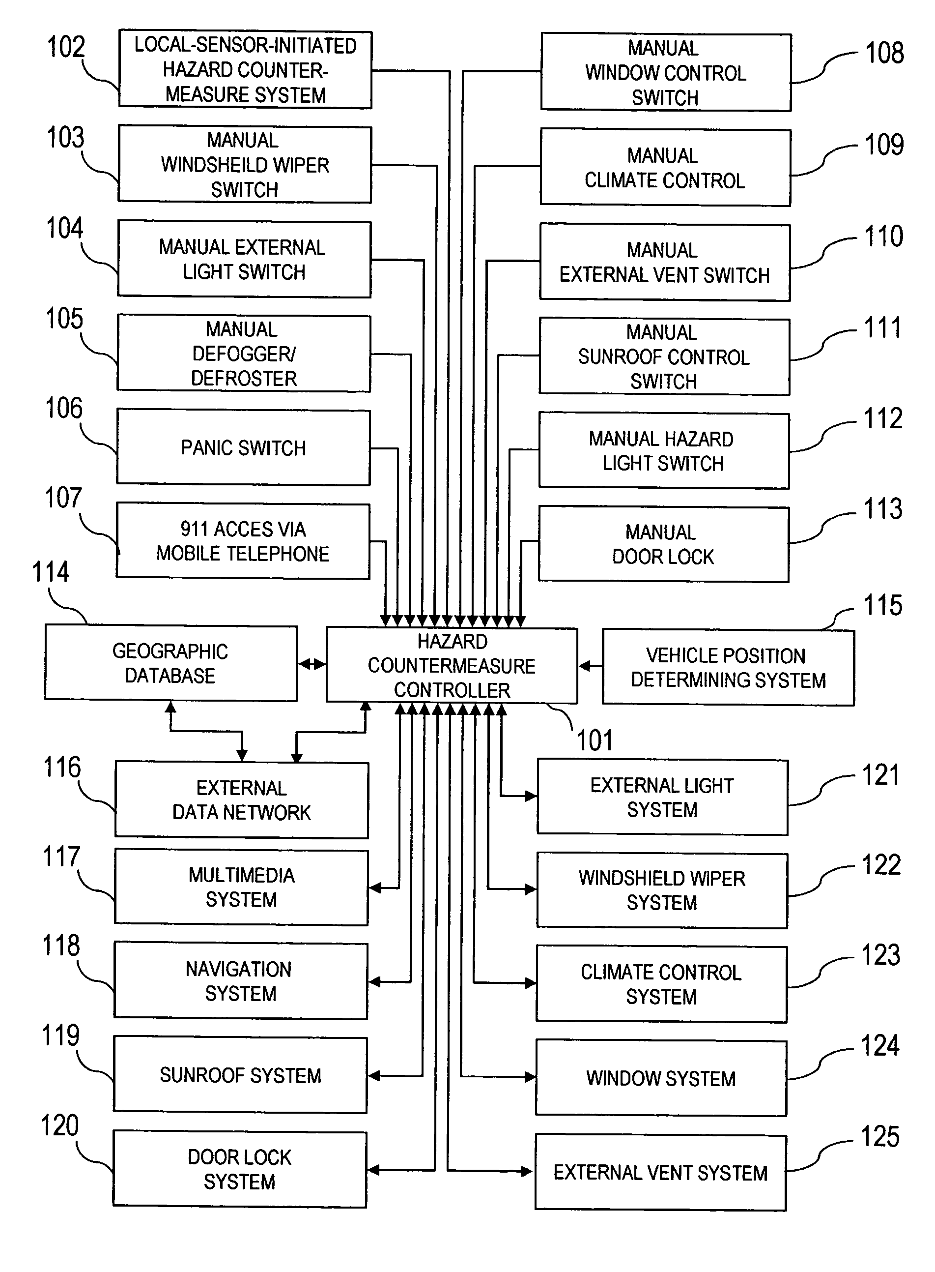
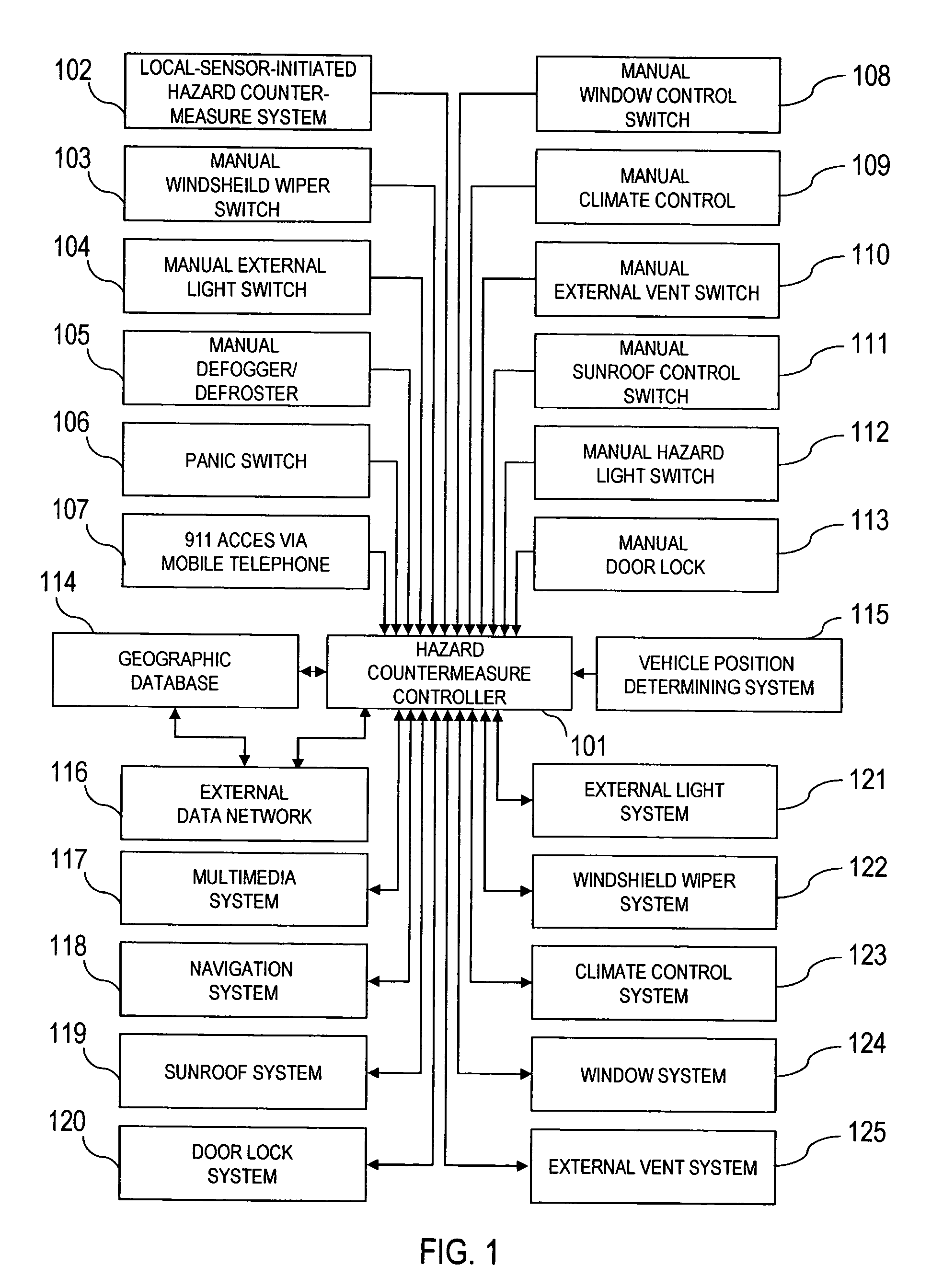
[0026]FIG. 1 is a block diagram that shows the information flow from manually activated switches 103-113 or the local-sensor-initiated hazard countermeasure to the hazard countermeasure controller 101. When an event issues from one of these manually or automatically activated systems, indicating a possible response to a hazard, the position of the vehicle is acquired from the vehicle position determining system 115. This information is then transmitted with a time stamp to the geographic database 114, and to the external data network 116 employing TDMA, CDMA, GSM or other cellular telephone networks, or employing wireless protocols for data transmission such as 802.11a / b, 802.11x, 802.11g, DSRC or other similar digital wireless communication means. Alternatively, the external data netwo...


PUM


Abstract

A control system that activates countermeasures to hazards indicated by a database and by information systems external to the vehicle by activating a plurality of vehicle systems. The control system analyzes location and time information regarding multiple situations that may coincide with the path of the vehicle and controls vehicle systems to provide countermeasures to hazards when probability of encountering those hazards meets a sufficient threshold.

Description

CROSS REFERENCE TO RELATED APPLICATION[0001]This application claims the benefit of the filing date of Provisional Patent Application Ser. No. 60 / 481,115, entitled Hazard Countermeasures System for Vehicles, filed on Jul. 21, 2003, which application is incorporated herein by reference in its entirety.BACKGROUND OF INVENTION[0002]1. Field of the Invention[0003]This invention relates to a vehicle control system and method that employs information available on a data network external to the vehicle, in conjunction with a geographic database and a system for determining the position and velocity of the vehicle to activate countermeasures to long-term and transient hazards that the control system determines the vehicle is likely to encounter.[0004]2. Description of the Prior Art[0005]U.S. Pat. No. 6,587,573 discloses a system and method of automatically controlling vehicle lights on the basis of an image sensor on-board the vehicle. The system does not use an external data network to dete...

Claims


Application Information

Patent Timeline
Patent Type & Authority Patents(United States)
IPC IPC(8): G01C21/00G08G1/0967
CPCB60H1/00771G08G1/096775G08G1/096741G08G1/096725
Inventor GRAY, JUSTIN
Owner GRAY JUSTIN
Learn More