Dynamic optical waveguide sensor

a technology of optical waveguide and optical waveguide, which is applied in the direction of instruments, fluid pressure measurement, optical elements, etc., can solve the problem that the technique may not be suitable for all applications

Inactive Publication Date: 2007-11-27
WEATHERFORD TECH HLDG LLC
View PDF4 Cites 11 Cited by
  • Summary
  • Abstract
  • Description
  • Claims
  • Application Information

AI Technical Summary

Problems solved by technology

While the foregoing pressure sensing techniques are beneficial, those techniques may not be suitable for all applications.

Method used


Image

  • Dynamic optical waveguide sensor
  • Dynamic optical waveguide sensor
  • Dynamic optical waveguide sensor

Examples


Embodiment Construction

[0016]The present invention provides for optical waveguide measurement systems that are suitable for sensing dynamically varying physical parameters such as pressure and strain. Some embodiments of the present invention enable both static and dynamic measurements of physical parameters. Embodiments of the present invention are suitable for use in harsh environments as found in oil and / or gas wells, engines, combustion chambers, etc.

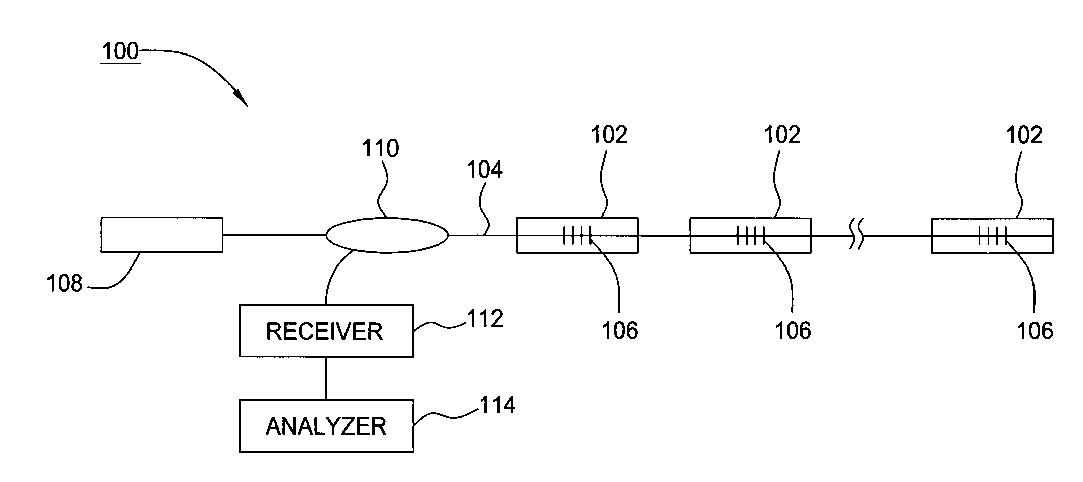
[0017]FIG. 1 illustrates an optical waveguide sensor system 100 having a sequence of sensors 102 disposed along an optical waveguide 104. Each sensor 102 includes at least one fiber Bragg grating 106. Depending on the application and the specific configuration, the sensor system 100 can be operated in various ways. For example, a tunable light source 108, such as a tunable laser or a broadband light source mated with a tunable filter, can inject light that is swept over a bandwidth into a coupler 110. The coupler 110 passes the light onto the optical wave...


PUM


Abstract

Methods and apparatuses that sense physical parameters, such as pressure and strain, using optical waveguide sensors are described. A light source emits light at a predetermined wavelength along an optical waveguide having a fiber Bragg grating optical sensing element. That sensing element reflects light in accord with a sloped shape function of reflected light amplitude verses wavelength. A receiver converts the reflected light into electrical signals and an analyzer then determines a physical parameter based on changes of amplitude of the reflected light. The analyzer also maintains the wavelength of the light such that the wavelength corresponds to a slope wavelength of the shape function.

Description

BACKGROUND OF THE INVENTION[0001]1. Field of the Invention[0002]Embodiments of the present invention generally relate to optical waveguide sensors, and more particularly to a fiber Bragg grating optical waveguide sensors that dynamically senses strain induced by a stimuli acting upon a transduction mechanism.[0003]2. Description of the Related Art[0004]A fiber Bragg grating (FBG) is an optical element that is formed by a photo-induced periodic modulation of the refractive index of an optical waveguide's core. An FBG element is highly reflective to light having wavelengths within a narrow bandwidth that is centered at a wavelength that is referred to as the Bragg wavelength. Other wavelengths pass through the FBG without reflection. The Bragg wavelength itself is dependent on physical parameters, such as temperature and strain, that impact on the refractive index. Therefore, FBG elements can be used as sensors to measure such parameters. After proper calibration, the Bragg wavelength...

Claims


Application Information

Patent Timeline
Patent Type & Authority Patents(United States)
IPC IPC(8): G02B6/00G02B6/34
CPCG01L1/246G01D5/35303G01D5/35316G01D5/35354G01L11/025
Inventor JONES, RICHARD T.
Owner WEATHERFORD TECH HLDG LLC
Why Eureka
Try Eureka