Screen change control apparatus and method using tabs

Inactive Publication Date: 2007-11-20
YAMAHA CORP
View PDF14 Cites 5 Cited by
  • Summary
  • Abstract
  • Description
  • Claims
  • Application Information

AI Technical Summary

Benefits of technology

[0004]In view of the foregoing, it is an object of the present invention to provide a screen change control apparatus and method which permit provision of a great may screens and also a quick switch between screens.
[0007]Namely, according to the present invention, a great number of screens (Y screens) are divided in advance into a plurality of screen groups (S screen groups). Thus, the present invention can selectively display any of screens corresponding to a great number of functions that is equivalent to a product between the number (T) of tabs within each screen group designatable by the second operator section and the number (S) of the screen groups. As a consequence, the present invention allows any apparatus, to which the present invention is applied, to have many functions corresponding in number to the product between the number (T) of tabs and the number (S) of the screen groups. Also, the present invention can greatly facilitate a search for any desired function by storing the groups of screens in association with particular functions. Further, by the provision of the first operator section dedicated to switching between the screen groups, the present invention can effect a quick shift or switchover to a desired screen group in a simplified manner; thus, the present invention allows the user to access a particular function at increased speed. As a result, the present invention not only permits storage of a multiplicity of function display screens, but also allows such stored display screens to be read out with a lesser number of operators (e.g., switches) to thereby greatly enhance the operability of an operation panel used.
[0008]According to another aspect of the present invention, the screen groups are arranged in predetermined order, and a determination is made as to whether there is any other designatable or displayable screen group before or after a currently designated screen group. Then, in accordance with the determination result, a shiftability indicating guide mark, such as a triangle mark, is displayed adjacent to the second operator section. With this arrangement, the present invention allows the user to readily identify the presence of any other designatable screen group adjoining (preceding or following) the currently designated screen group and thereby manipulate the operation panel with increased ease while imaging the order and arrangement of the screen groups.
[0009]The present invention is further characterized in that, even when a given screen group has been newly designated (i.e., there has been effected a switchover from one screen group to another) by activation of the first operator section, the one screen having been displayed up to the time of the designation of the give or other screen group is caused to remain displayed as before and the screen display is never renewed till next activation of the second operator section. With this arrangement, it is possible to preserve, as display history data, only a display screen necessary to the user and having been actually selected by activation of the second operator section. Further, there may be provided a display history tracing section, so that the user is allowed to quickly go back to a desired previous display screen by use of the history tracing section and thereby modify and confirm the current settings and operating states indicated by the previous display screen (backward operation step); the user can return to a current operation step quickly upon completion of the modification and confirmation of the previous display screen.

Problems solved by technology

Some of the conventional screen change techniques are arranged to permit a switchover to two screens of opposite natures through two screen switching actions, but, in this case, only a small number, equal to “the number of the tabs×2”, of screens can be provided, so that the number of available screens is limited considerably.

Method used


Image

  • Screen change control apparatus and method using tabs
  • Screen change control apparatus and method using tabs
  • Screen change control apparatus and method using tabs

Examples


Embodiment Construction

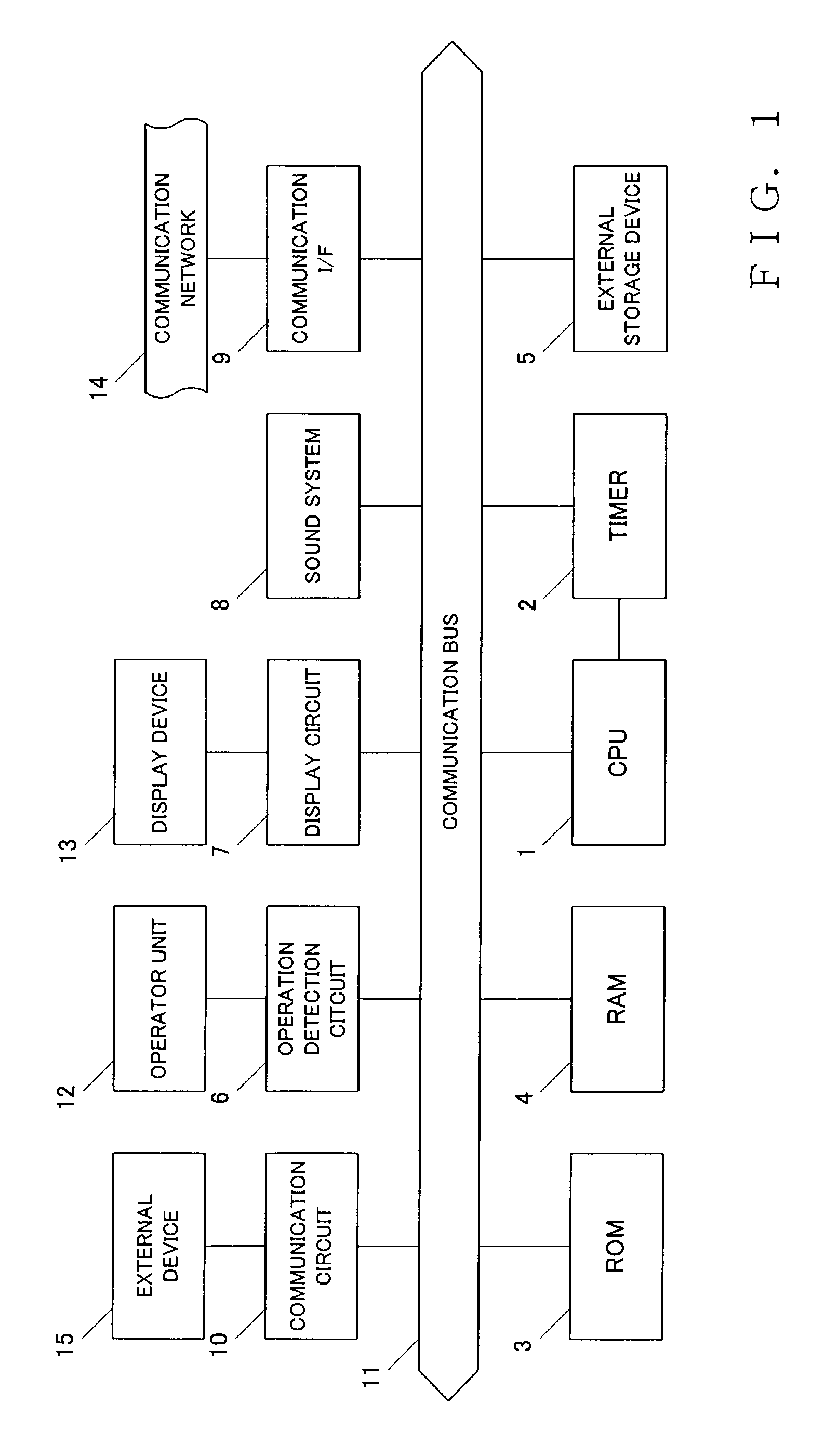
[0023]FIG. 1 is a block diagram showing a general hardware setup of a digital mixer equipped with an automatic performance function, to which is applied a screen-changing tab switch control apparatus in accordance with an embodiment of the present invention. This digital mixer includes a central processing unit (CPU) 1, a timer 2, a read-only memory (ROM) 3, a random access memory (RAM) 4, an external storage device 5, an operator operation detection circuit 6, a display circuit 7, a sound system 8, a communication interface (I / F) 9, a communication circuit 10, etc. and these mentioned components 1 to 10 are connected with each other via a communication bus 11.

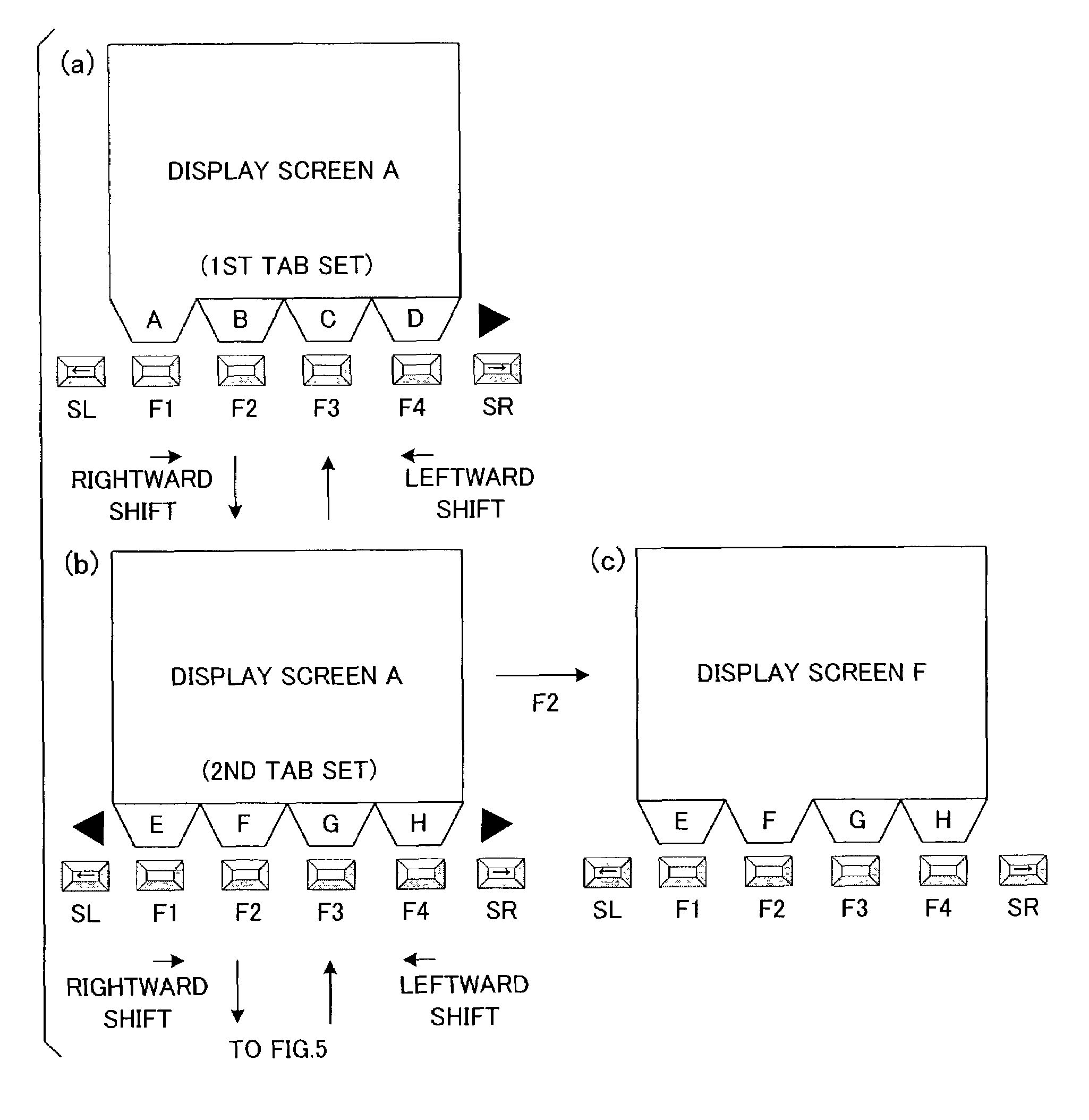
[0024]The CPU 1 controls behavior of the entire digital mixer, using clock pulses generated by the timer 2 and in accordance with predetermined software programs. The digital mixer carries out, in addition to normal digital mixing processing, screen-changing tab switch control processing that includes a shift switch depression...


PUM


Abstract

A plurality of displayable screens are classified into a plurality of screen groups in such a manner that two or more of the screens belong to each individual screen group. Once a desired one of the screen groups is designated by activation of a shift switch, respective tabs of the two or more screens belonging to the designated screen group are visually displayed on a display device. Then, once a desired one of the thus-displayed tabs is designated by activation of a tab switch, the screen corresponding to the thus-designated tab is displayed on the display device. Even when the tab display has been switched by designating another screen group, the screen corresponding to the last designated tab (i.e., main screen), is prevented from being changed unless another tab is designated.

Description

BACKGROUND OF THE INVENTION[0001]The present invention relates to an improved screen change apparatus and method which permit a quick screen change or switchover in a tone reproduction apparatus such as a digital mixer, and more particularly to a technique for performing screen change control through operation or activation of a tab switch.[0002]In many conventionally-known electronic sound signal processing apparatus, such as digital mixers, designed to reproduce musical tones, a tab (tab switch) is affixed to each of a great many screens (screen pages) showing respective current settings and operating states of a number of signal processing channels. When a user desires to ascertain the current settings and operating states of any desired one of the signal processing channels, he or she can operate or activate one of the tabs (tab switches) that corresponds to the desired processing channel, to thereby switch over to a display screen of the desired processing channel.[0003]However...

Claims


Application Information

Patent Timeline
IPC IPC(8): G06F3/048G06F3/00H03M11/04G06F3/023G06F3/033G06F3/0484H03M11/14
CPCG06F3/0483G06F3/0219
Inventor KOHYAMA, NAOHIDEHAMAMATSU, HIROSHI
Owner YAMAHA CORP
Why Eureka
Try Eureka