
Accelerator pedal module

Inactive Publication Date: 2007-11-20
ROBERT BOSCH GMBH
View PDF13 Cites 21 Cited by
  • Summary
  • Abstract
  • Description
  • Claims
  • Application Information

AI Technical Summary

Benefits of technology

[0006]In an exemplary embodiment described in DE 195 36 699 A1, already cited above, two elastic cheeks of the bearing block that each have a through bore must be bent open laterally, to enable introducing a bearing peg of the pedal lever into through holes of the cheeks. This elasticity in the region of the bearing faces requires a resilient bearing of the pedal lever on the bearing block. Since a sensor, which in the context of realizing an electrical accelerator pedal furnishes an electrical signal that is dependent on the actuation travel of the pedal lever to a central engine control unit is mounted on the accelerator pedal module, this kind of resilient support has an adverse effect on the measurement accuracy. In a preferred way, the elastic regions of the accelerator pedal module that make the snap closure possible are therefore located remotely from the bearing faces of the pivot connection, so that the bearing faces can be designed for a high rigidity that is favorable for the sake of measurement accuracy.
[0007]The elastic deformations that occur during the passage past one another of the associated stops can engender forces which change the relative position between the pedal lever and the bearing block during assembly. It is therefore especially preferable that the pedal lever can be braced on the bearing block by means of the bearing faces, before the pedal lever stop slides past the bearing block stop. The pedal lever is then guided in a defined way on the bearing block before the snap closure is completed, which facilitates assembly substantially.
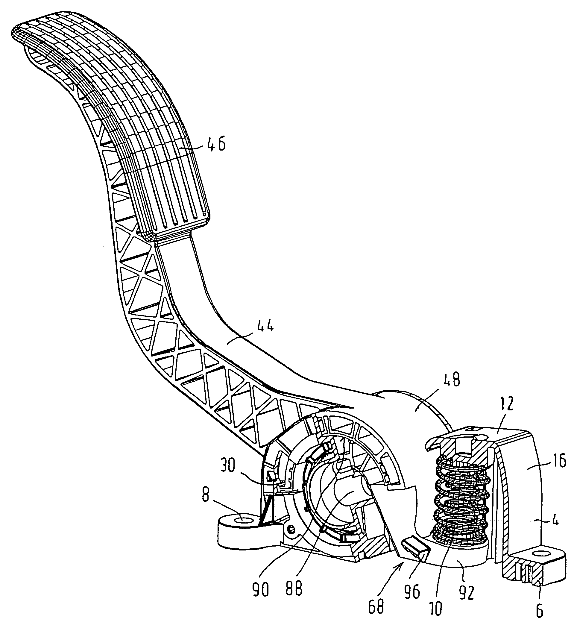
[0008]In a first embodiment, the bearing faces of the pivot connection include at least one annular portion, which is formed onto the pedal lever and extends over a partial circle and which can be introduced into an annular groove that is formed onto the bearing block and likewise extends over part of a circle. The result is an especially rigid, rail-like guidance of the pedal lever on the bearing block, which on the one hand facilitates assembly of the snap closure and on the other creates an especially rigid rotary support of the pedal lever on the bearing block.
[0009]In a further embodiment, the bearing faces of the pivot connection have a peg, which is coaxial with the pivot axis and is associated with the bearing block and on which a partly cylindrical bearing face of the pedal lever can be placed. The bearing surface of the pedal lever is then guided on the peg of the bearing block during the relative rotary motion that brings about the snap closure, which for the reasons given above substantially facilitates the assembly.
[0010]In a further provision, the bearing block preferably has two cheeks, between which the pedal lever is guided and which are provided with two protruding bearing block stops pointing toward one another. The symmetrical stops advantageously prevent the occurrence of a tilting moment when the pedal lever strikes a stop.

Problems solved by technology

Since a sensor, which in the context of realizing an electrical accelerator pedal furnishes an electrical signal that is dependent on the actuation travel of the pedal lever to a central engine control unit is mounted on the accelerator pedal module, this kind of resilient support has an adverse effect on the measurement accuracy.

Method used


Image

  • Accelerator pedal module
  • Accelerator pedal module
  • Accelerator pedal module

Examples


Embodiment Construction

[0021]The accelerator pedal module of the invention is used for controlling a driving engine, preferably an internal combustion engine of a motor vehicle, whose throttle valve is adjustable by a control motor. In that case, the accelerator pedal module serves to generate electrical signals for the control motor, so that the engine power can be controlled as a function of the position of an accelerator pedal of the accelerator pedal module. However, the driving engine can also for instance be an electric motor that is triggered by electrical signals.

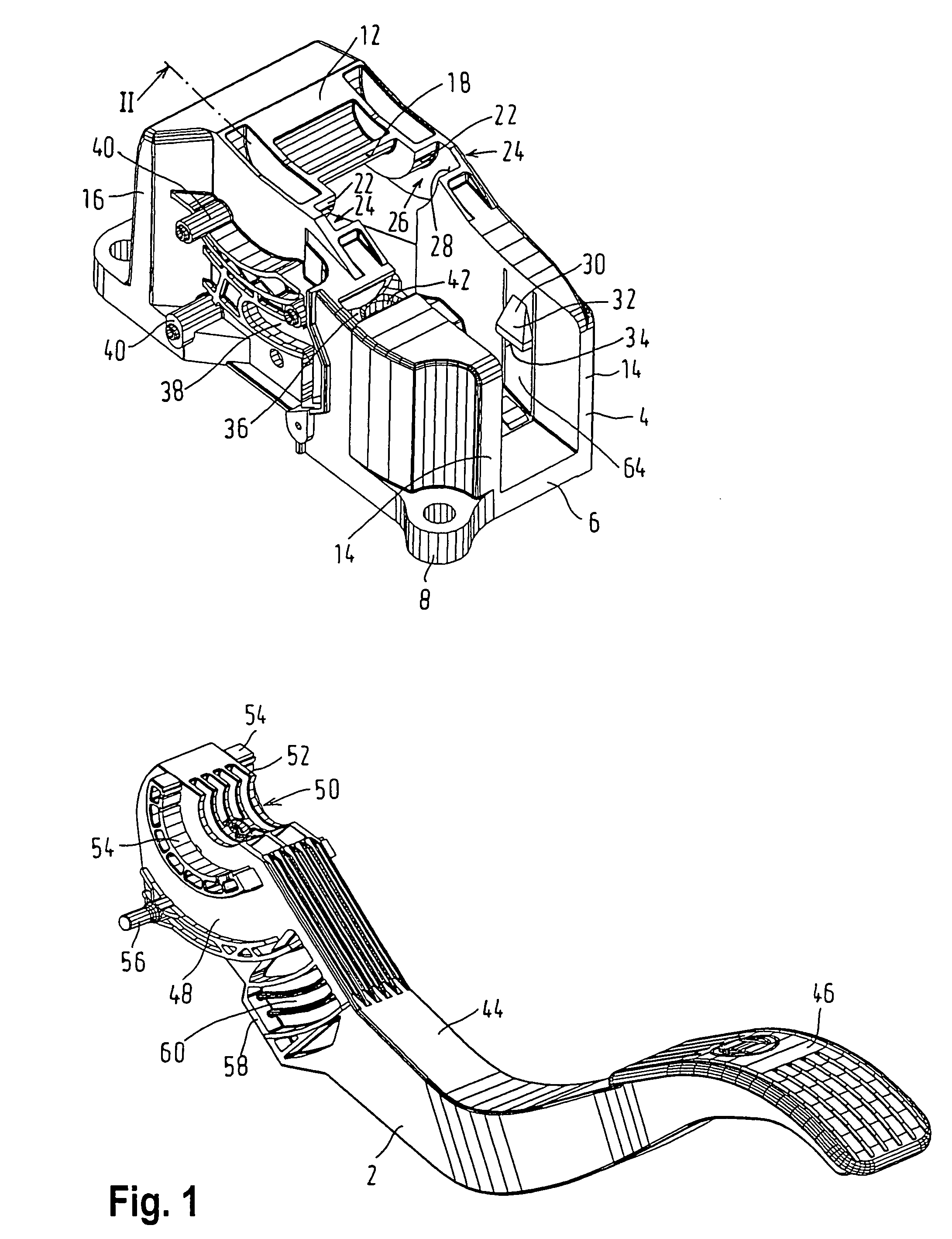
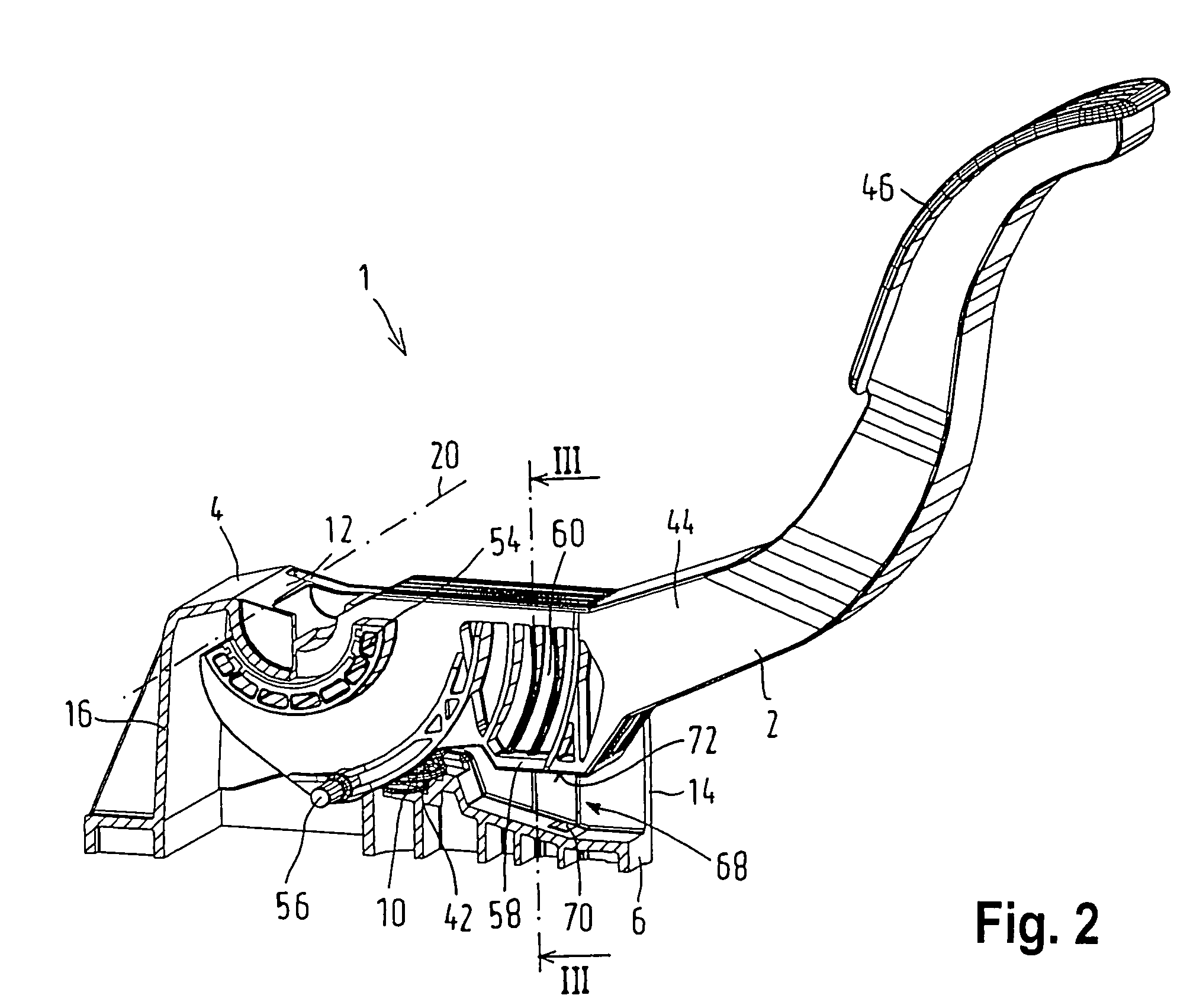
[0022]The accelerator pedal module 1 is foot-actuated by the motor vehicle's driver and as shown in FIG. 1 includes a pedal lever 2, which preferably is the gas pedal actuated directly by the driver's foot. Alternatively, the pedal lever 2 can be a lever of a lever mechanism or rod linkage mechanism that includes additional levers and is coupled to the gas pedal. The accelerator pedal module 1 also includes a bearing block 4 as a retentio...


PUM


Abstract

The invention relates to an accelerator pedal module for controlling the power of a driving engine having a pedal lever held rotatably about a pivot axis by means of a pivot connection on a bearing block, which pedal lever can be made to strike an associated bearing block stop by at least one pedal lever stop. In the region of the pedal lever stop and / or the bearing block stop, elasticities are present such that during a relative rotary motion executed about the pivot axis between the pedal lever and the bearing block to establish the pivot connection, the pedal lever stop slides past the bearing block stop because of elastic deformations and after springing back engages the bearing block stop from behind.

Description

BACKGROUND OF THE INVENTION[0001]1. Field of the Invention[0002]The invention is directed to an improved accelerator pedal module for controlling the power of a driving engine, in particular an internal combustion engine of a vehicle, having a pedal lever held rotatably about a pivot axis by means of a pivot connection on a bearing block, which pedal lever can be made to strike an associated bearing block stop by at least one pedal lever stop.[0003]2. The Prior Art[0004]One accelerator module of the type with which this invention is concerned is disclosed in German Patent Disclosure DE 195 36 699 A1.OBJECT AND SUMMARY OF THE INVENTION[0005]According to the invention, it is proposed that in the region of the pedal lever stop and / or the bearing block stop, elasticities are present such that during a relative rotary motion executed about the pivot axis between the pedal lever and the bearing block to establish the pivot connection, the pedal lever stop slides past the bearing block sto...

Claims


Application Information

Patent Timeline
IPC IPC(8): G05G1/30B60K26/02F02D11/02G05G1/46
CPCB60K26/02F02D11/02G05G1/46G05G1/38Y10T74/20888Y10T74/20534
Inventor CABA, RADEKROSSMUELLER, JOSEFCIZEK, VACLAVKOVAR, PETRSOLTA, ROSTISLAV
Owner ROBERT BOSCH GMBH
Learn More