
System, method and apparatus to implement low power high performance transceivers with scalable analog to digital conversion resolution and dynamic range

a high-performance transceiver and high-performance technology, applied in the field of system, method and apparatus to implement low-power high-performance transceivers with scalable analog to digital conversion resolution and dynamic range, can solve the problems of complex defining the interface between the two sections of the receiver, the characteristics of the amplifier will very likely change with temperature and aging, and the contribution of substantially to the cost of the receiver, so as to achieve the effect of keeping the power consumption of the system at a minimum

Active Publication Date: 2007-11-13
OSTENDO TECH INC
View PDF10 Cites 30 Cited by
  • Summary
  • Abstract
  • Description
  • Claims
  • Application Information

AI Technical Summary

Benefits of technology

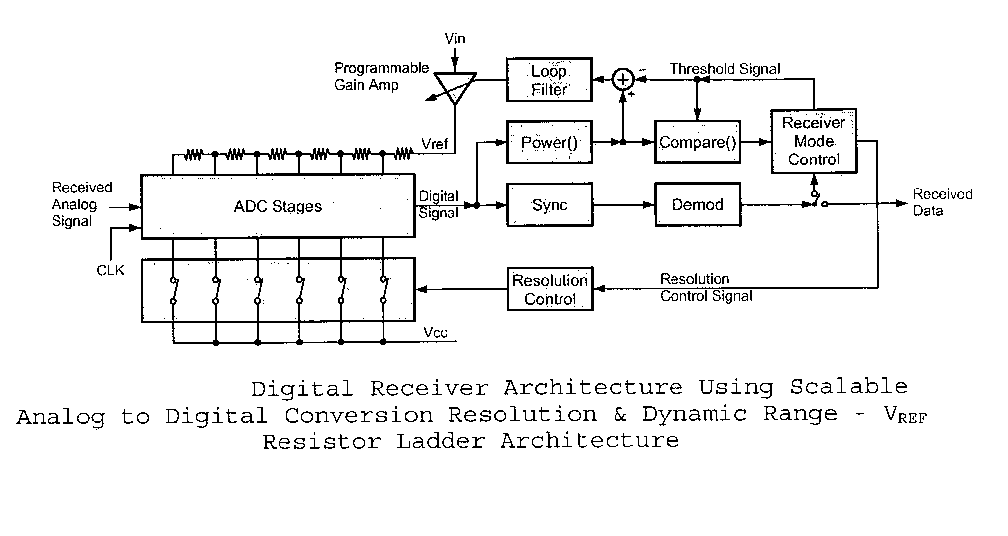
The present invention is about a digital communication receiver that has multiple modes of operation to minimize power consumption. It uses the lowest power for each mode to perform tasks associated with it. The invention also provides novel architectures for scalable resolution A / D converters and controlling the dynamic range of A / D converters. The invention also includes novel architectures for alleviating difficulties associated with AGC control loops. The patent text describes multiple embodiments of the invention.

Problems solved by technology

Previously, receiver design involved a tradeoff between power consumption in the idle mode and the signal precision when receiving a signal of interest.
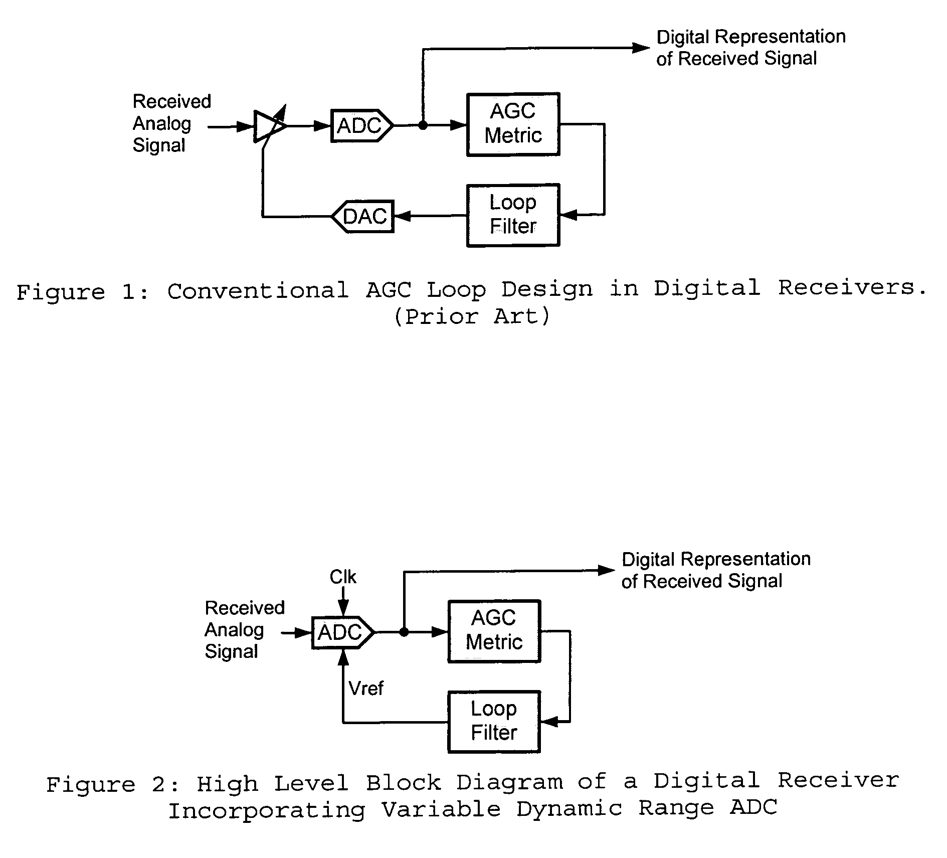
Several problems can be attributed to the AGC Loop of FIG. 1.
That normally contributes substantially to the cost of the receiver.
Furthermore, the characteristics of the amplifier will very likely change with temperature and with aging.
This causes complexity in defining the interface between the two sections of the receiver typically done by two design teams.

Method used


Image

  • System, method and apparatus to implement low power high performance transceivers with scalable analog to digital conversion resolution and dynamic range
  • System, method and apparatus to implement low power high performance transceivers with scalable analog to digital conversion resolution and dynamic range
  • System, method and apparatus to implement low power high performance transceivers with scalable analog to digital conversion resolution and dynamic range

Examples


Embodiment Construction

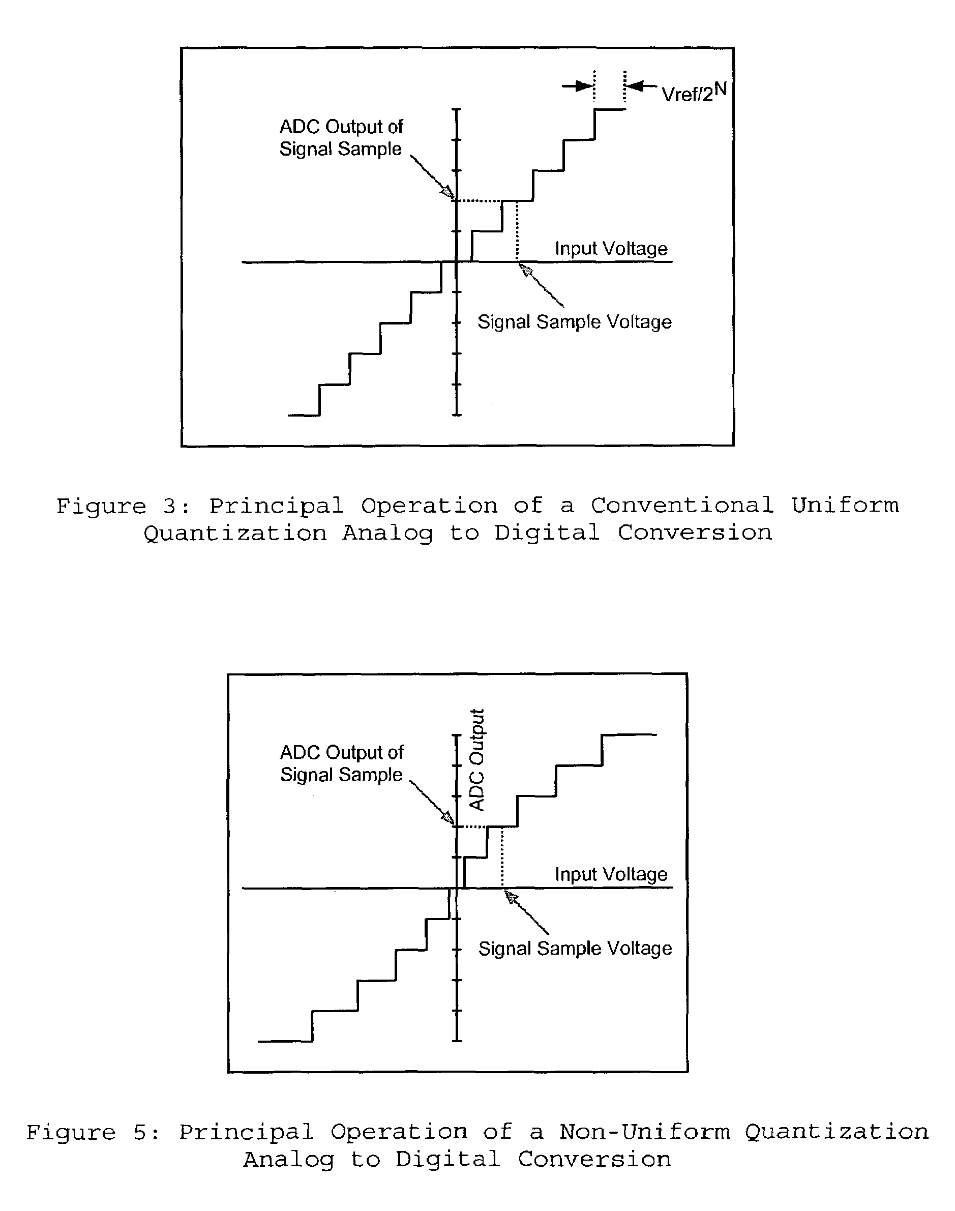
[0016]The present invention relates to a system, method, and apparatus to implement low power high performance transceivers with scalable analog to digital conversion resolution and dynamic range. As used herein, “Scalable Resolution” means is the ability to change the number of bits that are associated with the data conversion from analog to digital. “Scalable Dynamic Range” means the ability to change the dynamic range of the analog to digital conversion process in terms of the full voltage swing of the input analog signal. Also, as used herein, the words “mode” and “state” have the same meaning, and may be used interchangeably.

[0017]In this invention, a method of operating in a low power mode when the receiver is in the search mode, and operating in a high precision mode when the receiver is in the reception mode is disclosed. The proposed method can be implemented by running an A / D converter in the low power mode in the search mode, and by running the A / D converter in the high p...


PUM


Abstract

The present invention provides for operation of a digital communication receiver having multiple operational modes so that power consumption of the system can be kept at a minimum by using the lowest power operation for the system components performing tasks associated with each of the respective one of the multiple operational modes. An example is the receiver A / D converter operation with the lowest power to provide the desired resolution. Also, the invention provides novel architectures for implementing scalable resolution A / D converters. Furthermore, the invention generally includes a novel architecture for controlling the dynamic range of an A / D converter. In addition, the invention generally involves novel architectures for controlling the dynamic range of an A / D converter to alleviate difficulties associated with AGC control loops. Multiple exemplary embodiments are disclosed.

Description

CROSS-REFERENCE TO RELATED APPLICATION[0001]This application claims the benefit of U.S. Provisional Patent Application No. 60 / 352,724 filed Jan. 29, 2002.BACKGROUND OF THE INVENTION[0002]1. Field of the Invention[0003]The present invention relates to a system, method, and apparatus to implement low power high performance transceivers with scalable analog to digital conversion resolution and dynamic range.[0004]2. General Background[0005]A typical communications receiver operates in multiple modes wherein several different criteria of performance are suitable for each of the modes. For example, in a wireless LAN transceiver, it is desirable to have as little power consumption as possible during the time intervals that the receiver is scanning for a signal of interest (a.k.a. scanning mode, hereafter the search mode). The reason for this is that the transceiver can stay in the search mode for extensive time intervals. On the other hand, during the reception of a signal of interest (a....

Claims


Application Information

Patent Timeline
Patent Type & Authority Patents(United States)
IPC IPC(8): H04L27/08
CPCH03M1/181H03M1/007
Inventor EL-GHOROURY, HUSSEIN S.KARSI, MURAT F.
Owner OSTENDO TECH INC
Learn More