
Method, apparatus, and system for preserving cache data of redundant storage controllers

a data cache and controller technology, applied in the field of data storage systems, can solve the problems of data or instructions stored in failed cache memory, slow access to the memory of mass storage subsystems, data or instructions being lost,

Active Publication Date: 2007-11-06
XIOTECH CORP
View PDF10 Cites 54 Cited by
  • Summary
  • Abstract
  • Description
  • Claims
  • Application Information

AI Technical Summary

Benefits of technology

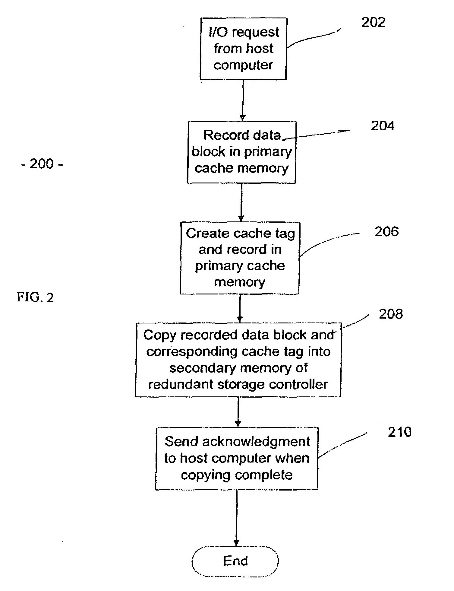
"The present invention provides a method for preserving cache data of redundant storage controllers without compromising the processing of host computer storage requests by the primary cache memory of an alternate, redundant storage controller. This is achieved by recording data blocks and cache tags in the primary cache memory of the receiving storage controller and copying them to the secondary cache memory of the alternate storage controller. This allows for seamless processing of storage requests from the host in case of failure of the primary cache memory."

Problems solved by technology

Unfortunately, access to the memory of the mass storage subsystems is slow, and as the sizes of the storage systems grow, access becomes even slower.
Some of these systems in particular include redundant cache controllers.
Unfortunately, in such configurations, if the shared cache memory itself fails, any data or instructions stored in the failed cache memory would be lost.
A significant challenge in such systems with redundant cache controllers is maintaining “cache coherency” without adversely affecting system performance.
These two implementations have an obvious problem; during the periodic transmission of the cache data from the main cache to each of the remaining redundant cache(s), the redundant cache(s) is (are) not available for receiving any storage requests from a host, resulting in an increase of processing time.
The first solution has additional problems.
Firstly, the overhead associated with the data transmissions counteracts the benefits of having a cache.
Secondly, the cache is not actually coherent at all times. That is, the data is vulnerable to loss during the sizeable period between transmissions.
Therefore it is apparent that a need exists in the art for a method and apparatus for preserving the dirty data of a failed redundant cache memory, which further reduces the overhead processing time of a data storage system and further increases system reliability.

Method used


Image

  • Method, apparatus, and system for preserving cache data of redundant storage controllers
  • Method, apparatus, and system for preserving cache data of redundant storage controllers
  • Method, apparatus, and system for preserving cache data of redundant storage controllers

Examples


Embodiment Construction

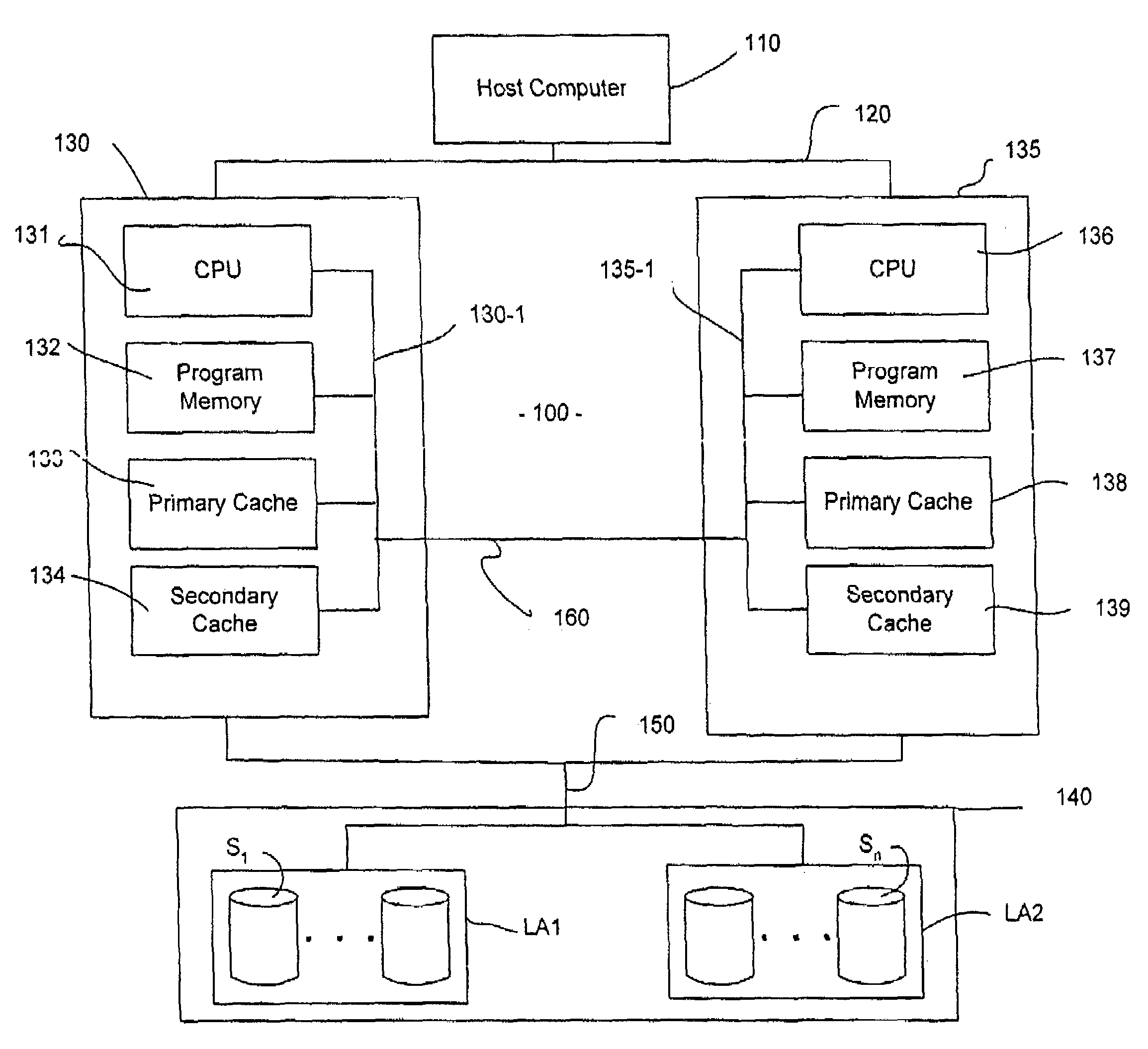
[0018]FIG. 1 depicts a high-level block diagram of a storage subsystem having redundant storage controllers each including a primary and secondary cache memory in accordance with an embodiment of the present invention. In the storage subsystem 100 shown in FIG. 1, a host computer 110 is coupled by a bus 120 to a first storage controller 130 and a second storage controller 135 (two controllers being shown by way of example only). Each of the storage controllers 130 and 135 is coupled to each of a plurality of storage units S1-Sn in an array 140 by an I / O bus (or busses) 150. Array 140 is divided into logical array one (LA1) and logical array two (LA2). In the embodiment illustrated, LA1 is associated with the first storage controller 130, and LA2 is associated with the second storage controller 135. One of ordinary skill in the art will readily recognize that the interface bus 150 between the storage controllers 130 and 135 and disk array 140 (including disk drives S1-Sn) may be any ...


PUM


Abstract

A method, apparatus, and system for preserving the cache data of redundant storage controllers, by copying the recorded data blocks and the associated cache tags in the primary cache memory of a storage controller to a secondary cache memory of an alternate, redundant storage controller, wherein upon a failure occurring in the primary cache memory of any of the storage controllers, subsequent storage requests from a host, previously intended for processing by the failed storage controller, are processed through the secondary cache memory of a non-failed, redundant storage controller that contains the failed storage's controller cache data and cache tags.

Description

[0001]This application claims benefit of U.S. Provisional patent application No. 60 / 379,001, filed May 8, 2002, which is herein incorporated by reference. This patent application is a Continuation-In-Part of U.S. patent application Ser. No. 10 / 430,487, filed May 5, 2003, now issued as U.S. Pat. No. 7,162,587.BACKGROUND OF THE INVENTION[0002]1. Field of the Invention[0003]The present invention generally relates to data storage systems, and more particularly, to storage systems that store redundant data.[0004]2. Description of the Related Art[0005]Modern mass storage subsystems are used within computer networks to provide increasing storage capacities to fulfill user demands from host computer system applications. Unfortunately, access to the memory of the mass storage subsystems is slow, and as the sizes of the storage systems grow, access becomes even slower. A cost effective solution to this problem provides a cache between the host computer and the storage system. The primary purp...

Claims


Application Information

Patent Timeline
Patent Type & Authority Patents(United States)
IPC IPC(8): G06F12/16G06F12/08G06F11/20
CPCG06F11/2092G06F11/1666G06F11/20G06F12/0866G06F11/2097
Inventor HICKEN, MICHAEL S.SNEAD, JAMES N.
Owner XIOTECH CORP
Learn More