
Image forming apparatus having a sheet removal portion

a technology of image forming apparatus and removal portion, which is applied in the direction of electrographic process apparatus, instruments, optics, etc., can solve the problems of difficult to difficult to consider pertinent configuration, complicated configuration at a surrounding of a transcribing device, etc., to achieve excellent use, simplify the configuration of the transcribing device mounted to the opening and closing member, and achieve stable sheet carrying function.

Inactive Publication Date: 2007-11-06
RICOH PRINTING SYST
View PDF8 Cites 5 Cited by
  • Summary
  • Abstract
  • Description
  • Claims
  • Application Information

AI Technical Summary

Benefits of technology

The solution simplifies the transcribing device configuration, enhances user accessibility, maintains stable sheet carrying, and prevents premature wear of the photosensitive belt by allowing controlled exposure during maintenance.

Problems solved by technology

However, in the case of JP-A-2003-186371, the exterior cover provided to be openably and closably is mounted with the transfer belt device configured by a belt, a plurality of rollers for supporting the belt and a transcribing roller or the like and therefore, a configuration at a surrounding of a transcribing device becomes complicated and the configuration is hardly regarded as pertinent in view of providing an inexpensive image forming apparatus.
Therefore, there is a case of bringing the pairs of rollers into contact with each other in a state of being shifted from each other delicately depending on a way of closing the exterior cover and there is a drawback that a stable sheet carrying function is difficult to achieve.
Further, also dimensional accuracies between the respective rollers are difficult to be achieved by being involved with attaching and detaching operation accompanied by opening and closing the exterior cover.

Method used


Image

  • Image forming apparatus having a sheet removal portion
  • Image forming apparatus having a sheet removal portion
  • Image forming apparatus having a sheet removal portion

Examples


Embodiment Construction

[0015]An explanation will be given of embodiments of the invention in reference to the drawings as follows.

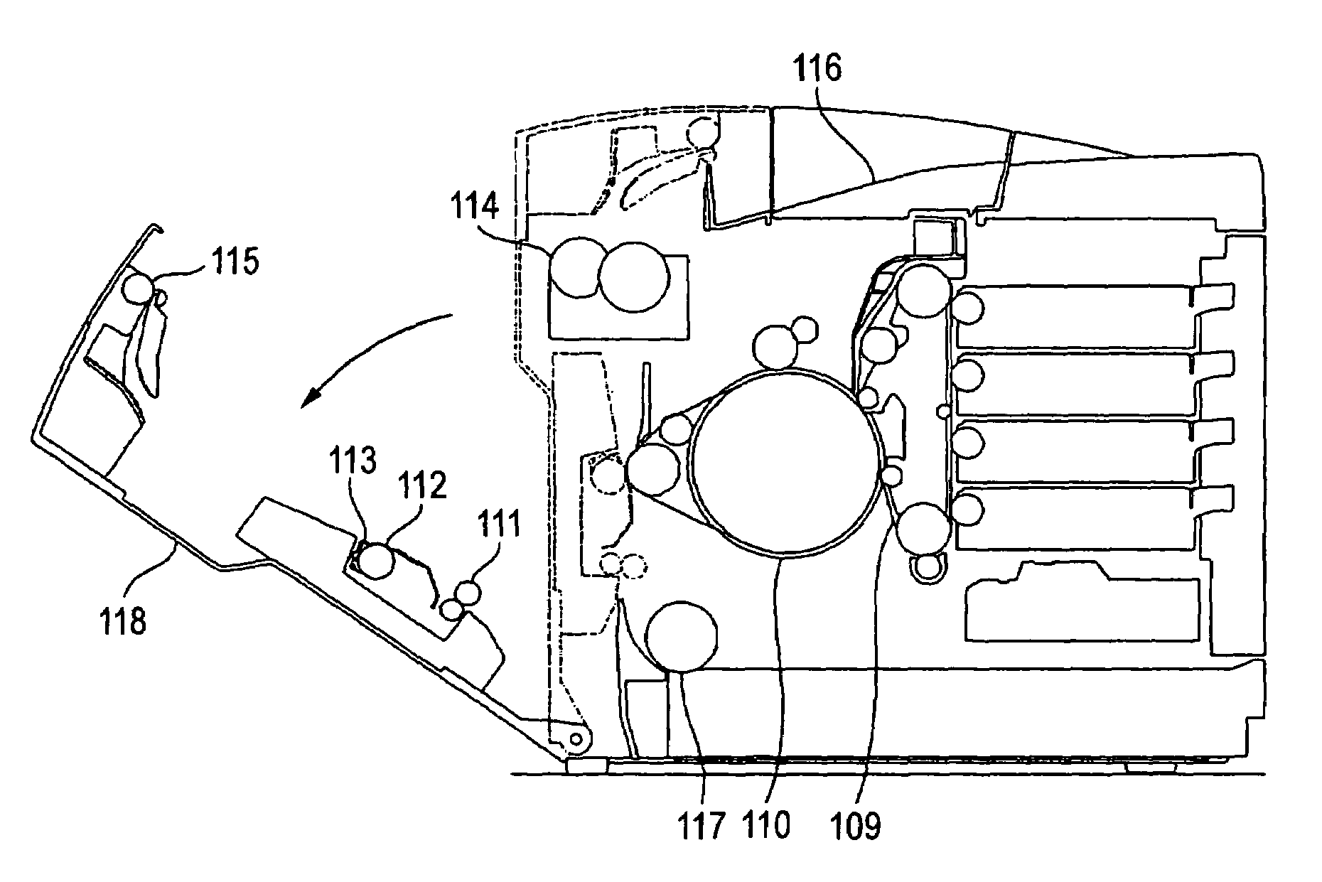
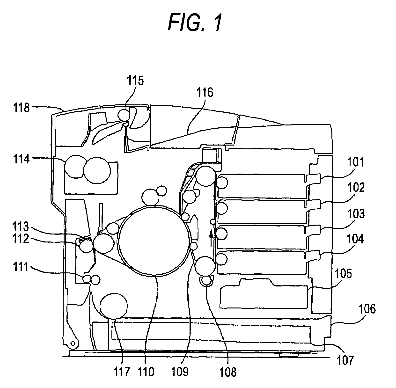
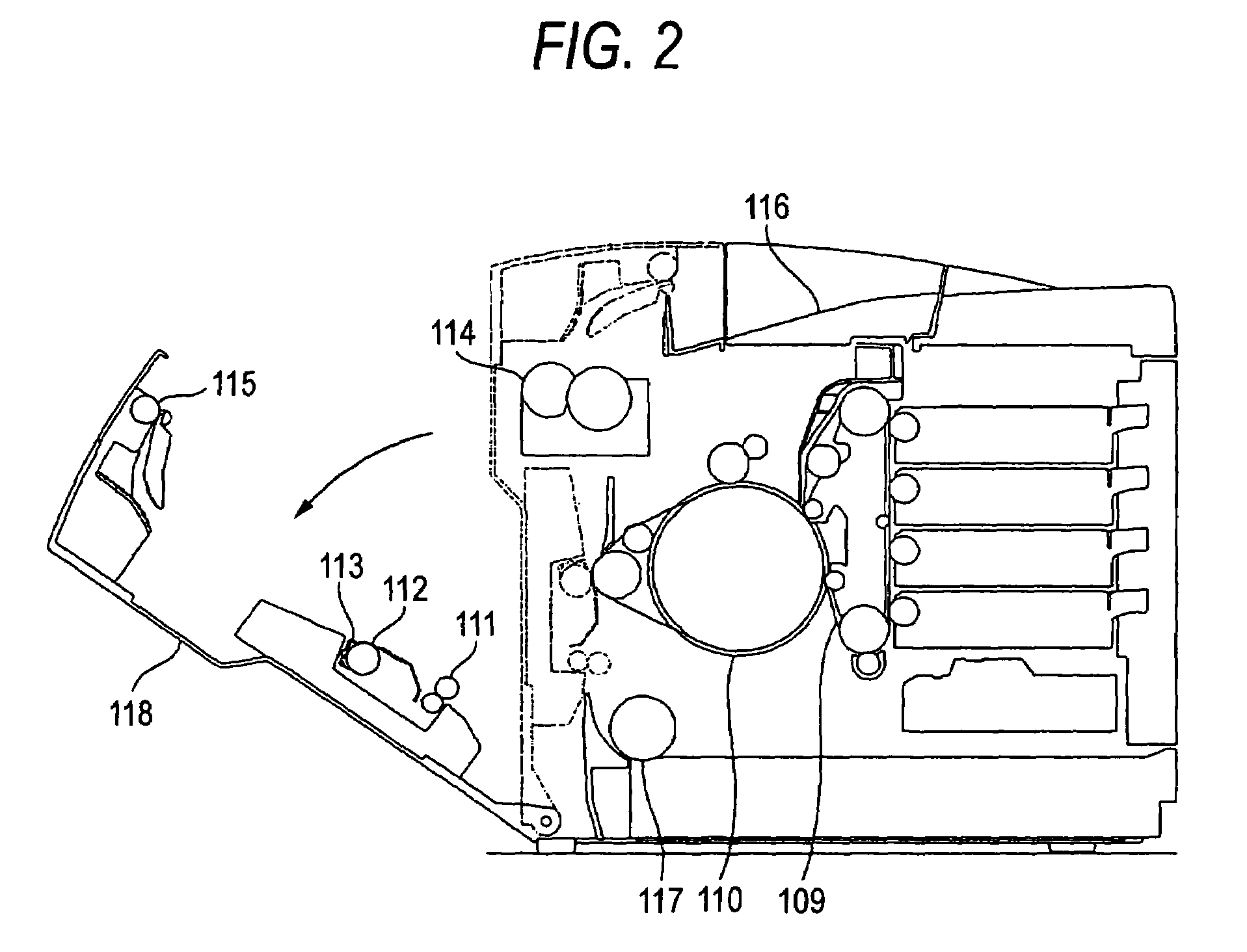
[0016]First, an explanation will be given of a total configuration of an image forming apparatus in reference to FIG. 1. In FIG. 1, numeral 109 designates a photosensitive belt which is supported to be able to move endlessly in an arrow direction. Numeral 108 designates a charger and the charger 108 uniformly charges a surface of the photosensitive belt 109 by a printing start signal from a host. An optical unit 105 for irradiating light to the surface of the charged photosensitive belt 109 exposes the photosensitive belt 109 in accordance with printing data from the host to form an electrostatic latent image on the surface of the photosensitive belt 109.

[0017]The electrostatic latent image formed on the photosensitive belt 109 is supplied with a toner of any color of developing unit 101, 102, 103, 104 to be visualized as a toner image and is carried to a region at which the ph...


PUM


Abstract

An image forming device includes an openable panel disposed on a side of the image forming device. The panel includes a pair of carrying rollers, a transcribing roller and a pair of discharging sheet carrying rollers.

Description

BACKGROUND OF THE INVENTION[0001]1. Field of the Invention[0002]The present invention relates to an image forming apparatus. Particularly, it more specifically relates to an improvement in an image forming apparatus including an opening and closing portion that remove the sheet remaining in the apparatus.[0003]2. Description of the Related Art[0004]In an image forming apparatus, it is general to include an opening and closing portion of a door, a cover or the like to be able to simply remove the sheet remaining in the apparatus by a failure in carrying the sheet or the like by a user. For example, according to JP-A-2003-186371, there is described a configuration of an opening and closing portion in which a driven roller constituting a pair of registration rollers, a transfer belt device and an upper roller constituting a pair of sheet discharging rollers are provided to an exterior cover, and when the exterior cover is opened, a sheet carrying path from a sheet feeding portion to a ...

Claims


Application Information

Patent Timeline
Patent Type & Authority Patents(United States)
IPC IPC(8): G03G21/00G03G15/00G03G21/16
CPCG03G15/6529G03G2215/00548G03G2215/00544
Inventor HASHIMOTO, HARUOWAKAMATSU, KAZUHIROOKANO, TADASHIIKEMATSU, TAKAMITSUUKEI, SHOJI
Owner RICOH PRINTING SYST
Learn More