
Circuits, systems, methods, and software for power factor correction and/or control

a technology of power factor and power converter, applied in the field of power factor correction and/or control, can solve the problems of wasting power/energy, noise entering the power line, and a portion of transmitted energy is wasted, so as to reduce and/or minimize the current period, reduce noise, and minimize the thd of the power converter

Active Publication Date: 2007-11-06
MARVELL ASIA PTE LTD
View PDF8 Cites 126 Cited by
  • Summary
  • Abstract
  • Description
  • Claims
  • Application Information

AI Technical Summary

Benefits of technology

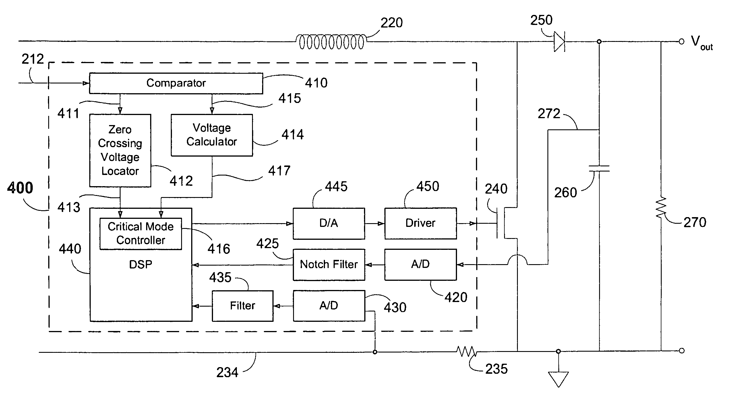
The present invention relates to circuitry, architectures, systems, methods, algorithms, and software for correcting and controlling a power factor in AC-DC boost converters. The invention takes a computational approach to reducing or minimizing zero current periods in the critical mode of power converter operation, which helps to reduce the THD of the power converter and minimize noise that may be injected back into AC power lines. The technical effects of the invention include improved efficiency, reduced noise, and improved performance of power converters.

Problems solved by technology

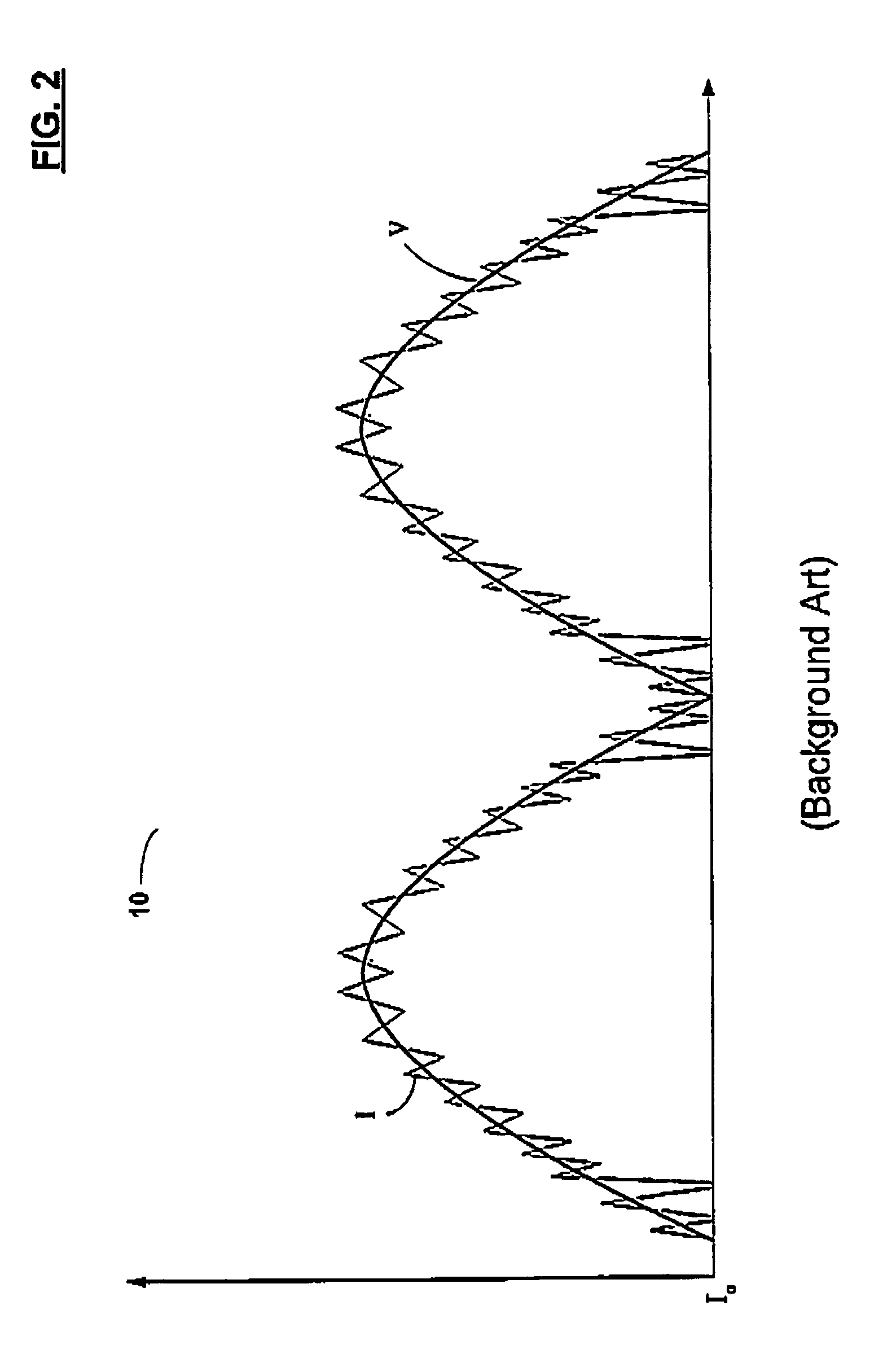
In such situations, transmitted power / energy can be wasted (due to phase mismatch between current and voltage) and / or noise may be introduced into the power line.
When the PF does not approach 1, even under limited conditions, some portion of the transmitted energy is wasted, and current that should be passed onto a load may be returned, thereby introducing noise onto the power line.
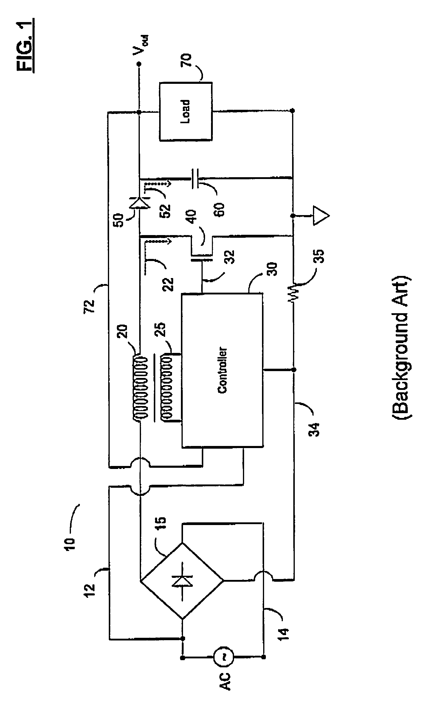
Moreover, if the THD is sufficiently high, noise can be fed back onto the AC power lines 12-14, a highly undesirable result from the perspective of a systems designer (e.g., of a power line network).
However, this approach suffers from the inevitable latency that all transformer coils experience when sensing a current in another coil, necessarily introducing some positive length of time in the zero current period 126 (see FIG. 3A) and introducing some noise back into the AC power line 12-14.
However, the current and voltage values at node 34 are relatively low in the critical mode of operation, thereby increasing the relative error in current determinations at node 34 to a level where such determinations may not be sufficiently accurate for commercially successful applications.

Method used


Image

  • Circuits, systems, methods, and software for power factor correction and/or control
  • Circuits, systems, methods, and software for power factor correction and/or control
  • Circuits, systems, methods, and software for power factor correction and/or control

Examples


Embodiment Construction

[0023]Reference will now be made in detail to the preferred embodiments of the invention, examples of which are illustrated in the accompanying drawings. While the invention will be described in conjunction with the preferred embodiments, it will be understood that they are not intended to limit the invention to these embodiments. On the contrary, the invention is intended to cover alternatives, modifications and equivalents, which may be included within the spirit and scope of the invention as defined by the appended claims. Furthermore, in the following detailed description of the present invention, numerous specific details are set forth in order to provide a thorough understanding of the present invention. However, it will be readily apparent to one skilled in the art that the present invention may be practiced without these specific details. In other instances, well-known methods, procedures, components, and circuits have not been described in detail so as not to unnecessarily ...


PUM


Abstract

Circuits, systems, methods and software for controlling a power conversion and / or correcting and / or controlling a power factor in such conversion(s). The present invention generally takes a computational approach to reducing or minimizing zero current periods in the critical mode of power converter operation, and advantageously reduces zero current periods in the critical mode of power converter operation, thereby maximizing the power factor of the power converter in the critical mode and reducing noise that may be injected back into AC power lines. The present power factor controller allows for greater design flexibility, reduced design complexity, and reduced resolution and greater tolerance for error in certain parameter measurements useful in power factor correction and / or control.

Description

RELATED APPLICATIONS[0001]This application may be related to U.S. application Ser. No. 10 / 804,660, filed Mar. 19, 2004, the relevant portions of which are incorporated herein by reference.FIELD OF THE INVENTION[0002]The present invention generally relates to the field of power factor correction and / or control. More specifically, embodiments of the present invention pertain to circuits, systems, methods, and software for correcting and / or controlling a power factor in alternating current (AC)-direct current (DC) conversions.DISCUSSION OF THE BACKGROUND[0003]An electrical load may appear to a power supply as a resistive impedance, an inductive impedance, a capacitive impedance, or a combination thereof. Ideally, when the current passing to the load is in phase with the voltage applied to or crossing the load, the power factor approaches one. Due to the nature of alternating current, the power factor of AC power can easily be less than one in certain situations (e.g., when the voltage ...

Claims


Application Information

Patent Timeline
Patent Type & Authority Patents(United States)
IPC IPC(8): G05F1/613G05F1/70
CPCG05F1/70H02M1/4225Y02B70/126Y02B70/10
Inventor CHEN, XIAOPENGLIN, JIANQING
Owner MARVELL ASIA PTE LTD
Learn More