Printer, a supply unit for the printer, and a member for accommodation in the supply unit

a technology for printing supplies and printers, which is applied in the direction of printing, other printing apparatus, web handling, etc., can solve the problems of perception errors resulting in faulty positioning that occur relatively rarely, and achieve the effect of simple determination, reduced number of errors, and accurate positioning of printer rolls

Inactive Publication Date: 2007-10-23
OCE TECH
View PDF12 Cites 0 Cited by
  • Summary
  • Abstract
  • Description
  • Claims
  • Application Information

AI Technical Summary

Benefits of technology

[0007]The advantage of the present invention is that the printer does not have to be provided with movable positioning aids and it is very simple for the user to accurately position a roll in the printer. This has the advantage that the manner for transporting the unwound web in the printer has to satisfy less stringent requirements. The present invention often serves to compensate for any inaccuracies in the initial position of the roll, which result in inaccurate positioning of the web in the print engine.
[0008]In one embodiment, the pattern is such that it includes at least three discrete transitions which differ from one another. This means that each discrete transition, including its adjoining pattern elements, differs from the other two transitions including their adjoining pattern elements. It has been found in this way that any mistakes in perception resulting in faulty positioning occur relatively rarely. Particularly in the case of rollers which are relatively small with respect to the length of the core, it has been found that the number of mistakes can be reduced relatively considerably.
[0009]In one embodiment, the pattern comprises at least three consecutive zones extending in the longitudinal direction of the member, the zones being separated from one another by the discrete transitions, which zones have a color indication differing from one another. It has been found that in this embodiment practically no faulty positionings should occur. Visual perceptible transitions, particularly accompanied by intermediate zones with different colors, other than in the case, for example, of pattern elements only in black and white (or colorless) appear to be very suitable for simple determination of when both projecting pattern parts are equal (at least mirror-image symmetrical) to one another. As a result, mistakes should occur only exceptionally, for example in the case of gross negligence of whoever places the roll on the core, or in the case of a special form of color blindness. In another embodiment, no zones having the same color indication occur in a series of consecutive zones in which there are at least three discrete transitions between the zones. As a result, the risk of faulty positioning is further reduced.
[0010]In one embodiment, each zone substantially encircles the member. In this embodiment, the member, at least an appreciable part thereof, is surrounded by the zones which, for example, each form a strip of a specific color. As a result, the position of the core with respect to the user positioning the roll on the core is practically no longer important, since the user can perceive the colored pattern on this core irrespective of the core position. This makes it an even more user-friendly way of placing the roll.
[0011]In one embodiment, the zones adjoin one another. In this embodiment, the colored zones are not separated by an unmarked zone. This appears to result in fewer mistakes. In addition, in this embodiment, the pattern can be disposed on the core in the form of a continuous element, for example in the form of a sticker, or if required in the form of two identical stickers each disposed on one side of the reference point.
[0012]In one embodiment, the web is rolled on a tube, whereby the tube is releasably fixed on the member. In this embodiment the web is wound on the tube in an earlier stage, for example in the factory where the receiving material is produced. The core has a format such that it fits in the tube, for example because the core is a cylinder the outer periphery of which is a fraction smaller than the inner periphery of the tube. The core can, for example, be provided with lugs distributed over its surface, said lugs being radially movable with the position thereof being lockable. By moving these lugs in the radial direction away from the core axis, when the tube has been pushed over the core, the tube is fixed to the core. Locking of the position of the lugs results in a permanent fixing. By unlocking this locking system and moving the lugs back in the direction of the core axis the tube is again released from the core and can be pushed off the core.

Problems solved by technology

It has been found in this way that any mistakes in perception resulting in faulty positioning occur relatively rarely.

Method used


Image

  • Printer, a supply unit for the printer, and a member for accommodation in the supply unit
  • Printer, a supply unit for the printer, and a member for accommodation in the supply unit
  • Printer, a supply unit for the printer, and a member for accommodation in the supply unit

Examples


Embodiment Construction

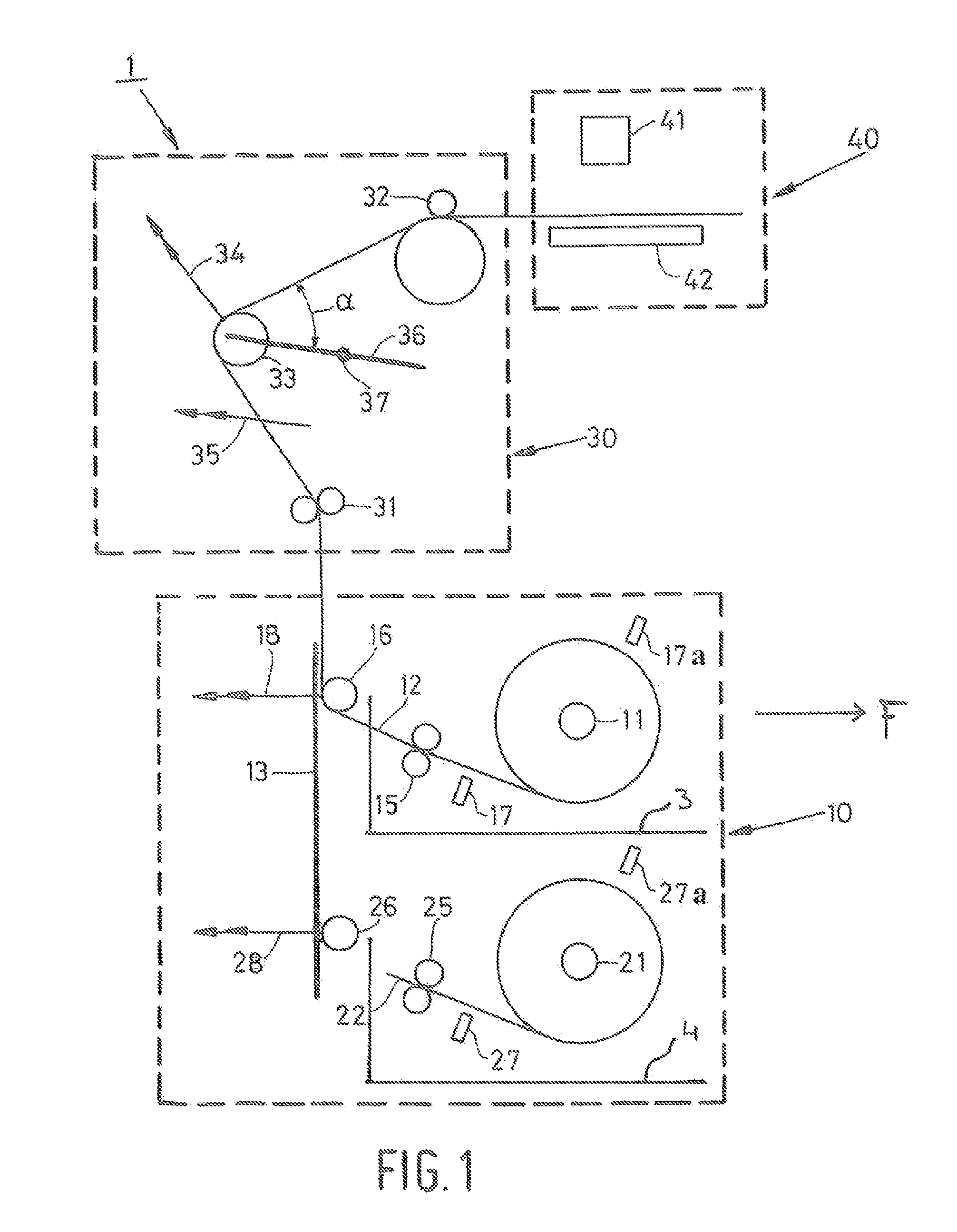
[0020]FIG. 1 is a diagram showing a printer according to the present invention. The printer is provided with a supply unit 10 which serves for storage and delivery of the substrate for printing. In addition the printer comprises transport unit 30 which transports the substrate from the supply unit 10 to the print unit 40. Unit 30 also ensures accurate positioning of the substrate in the print zone formed between the print surface 42 and the inkjet printhead 41. In this embodiment, print unit 40 is a conventional engine comprising printhead 41 which is constructed front a number of loose sub-heads, each for one of the colors black, cyan, magenta and yellow. A printhead of this type is described in detail in European patent application EP 1 378 360. Printhead 41 has only a limited print range so that it is necessary to print the image on the substrate in various sub-images. For this purpose, the substrate is transported in increments in each case in the transit direction (subscan dire...


PUM


Abstract

A printer including a print unit, a supply unit for holding a web of receiving material wound into a roll, a system for unwinding the web and transporting it for printing to the print unit, which supply unit is adapted to carry an elongate member on which the roll is fixed, substantially concentrically, the elongated member being provided at its peripheral edge with a pattern of sensorially perceptible discrete transitions, which pattern is substantially symmetrical with respect to a reference position on the elongated member and extends from this position to the vicinity of the ends of the elongated member.

Description

BACKGROUND OF THE INVENTION[0001]The present invention relates to a printer comprising a print unit, a supply unit for holding a web of receiving material wound into a roll, and a system for unwinding the web and transporting it for printing to the print unit, which supply unit is adapted to carry an elongated member on which the roll is fixed substantially concentrically. The present invention also relates to a supply unit for holding the receiving material and an elongate member comprising elements for releasable fixing of the receiving material.[0002]In one embodiment of a known printer, a roll of the receiving material is fixed, frequently prior to the placing of the roll in the supply unit, on an elongated member, particularly a cylindrical core, which can be received in bearer elements adapted for this purpose in the supply unit. To unwind the web, the core is rotatably accommodated in the bearer elements. During printing of the receiving material, the required quantity of mat...

Claims


Application Information

Patent Timeline
Patent Type & Authority Patents(United States)
IPC IPC(8): B41J15/00B41J2/315B41J29/00
CPCB41J11/0025B41J15/02B65H16/02B65H26/066B65H16/06B65H16/103B65H16/021B65H2801/12
Inventor HOLTMAN, LODEWIJK T.
Owner OCE TECH
Why Eureka
Try Eureka