
Position measuring system

Active Publication Date: 2007-10-23
DR JOHANNES HEIDENHAIN GMBH
View PDF8 Cites 8 Cited by
  • Summary
  • Abstract
  • Description
  • Claims
  • Application Information

AI Technical Summary

Benefits of technology

[0006]Therefore an object of the present invention is based on providing a position measuring system of the type mentioned at the outset, with which the installation in a machine to be equipped with the measuring system is made easier.
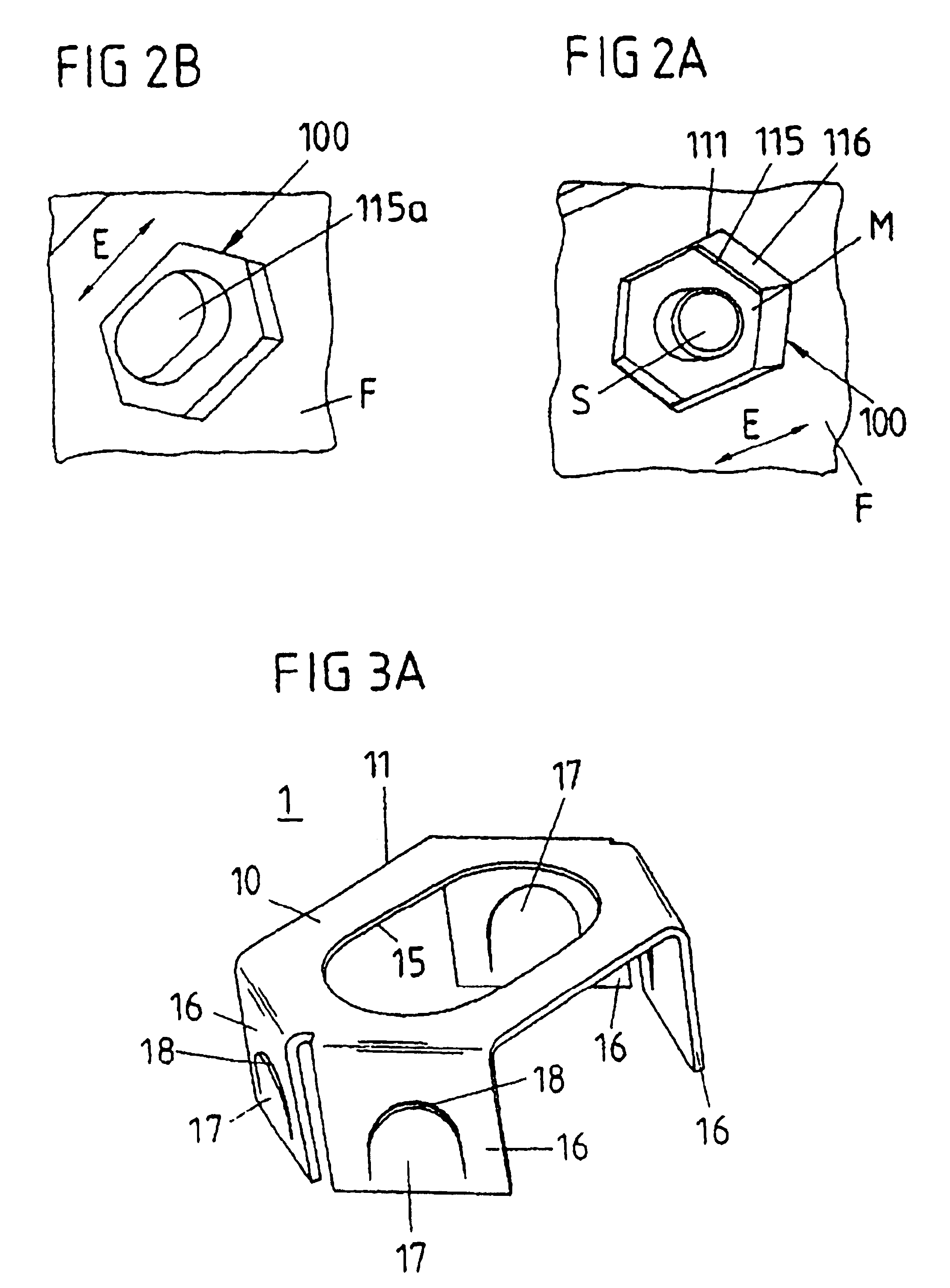
[0007]This object is attained in accordance with the present invention by the creation of a position measuring system for determining the position of a first structural component and a second structural component. The position measuring system includes a first support for receiving a first position measuring device, which is set up and provided for being fastened to the first structural component and a second support for receiving a second position measuring device, which is set up and provided for being fastened to the second structural component. The position measuring system further includes a first connector that fastens the first support to the first structural component and a second connector that fastens the second support to the second structural component, wherein the second connector includes a nut, with which a screw can be brought into engagement, wherein the nut is inserted into a recess of the second support. The position measuring system further includes a blocking element which, in an inserted state, works together with the nut in order to prevent a movement of the nut out of the recess in an axial direction, which is a direction of insertion of the screw into the nut, sufficiently far so that insertion of the screw into the nut is made possible.
[0008]The attainment of the object of the present invention mentioned previously makes a blocking element available in a cost-effective manner, which secures the nut inserted into the associated recess against falling out in the axial direction (with respect to the direction of extension of the screw to be turned into the nut or substantially perpendicular to the opening of the nut).
[0010]The ability of the nut to be shifted in the recess perpendicularly with respect to the axial direction of the associated screw for the purpose of a tolerance compensation is preferably achieved in that the nut is seated in the recess with a certain axial play (which can be as small as desired). A seating with axial play is here generally understood to be any seating of the nut in the recess which, because of the substantially loose arrangement of the nut in the recess, permits a shifting of the nut perpendicularly with respect to the axial direction, even if no substantial movement should be possible in the axial direction (because of an extremely limited axial play). Accordingly it is advantageous that the nut is not clamped (by axially acting forces) in the recess (between the bottom of the recess and the clip) in such a way that it can no longer be moved along the direction of extension of the recess.
[0013]The fixation in place of the clip on the interior wall of the recess can be advantageously achieved in that a sharp-edged outer rim of the clip is pushed (under prestress) against the interior wall of the recess in such a way that it is secure against slipping out in the axial direction. The clip is designed to be elastically deformable in at least one portion for providing a sufficient prestress.
[0019]To make the turning of the screw into the associated nut easier, a twisting guard is preferably provided, which prevents a rotating movement of the screw in the recess. For one, this twisting guard can be integrated into the recess itself, in particular in that the (for example polygonal) inner contour (encircling interior wall) of the recess is matched to the outer contour of the nut in such a way that it does not permit a rotating movement of the nut in the recess.

Problems solved by technology

In the course of installing such a position measuring system (in particular linear measuring system) in a machine tool, i.e. the fastening of the two supports (for example a longitudinally extending housing on the one hand and a mounting base on the other) to the structural components of the machine tool (for example a machine bed and a tool receiver) which can be moved with respect to each other, there often is too little space available between the individual machine elements for performing the assembly work.
Thus, when making a nut-screw connection it is often not possible to grasp the nut with a tool and to secure it against slipping or falling out of the associated recess until the associated screw has been screwed into the interior thread of the nut.
Often there is not sufficient space available for grasping the nut with the fingers.

Method used


Image

  • Position measuring system
  • Position measuring system
  • Position measuring system

Examples


Embodiment Construction

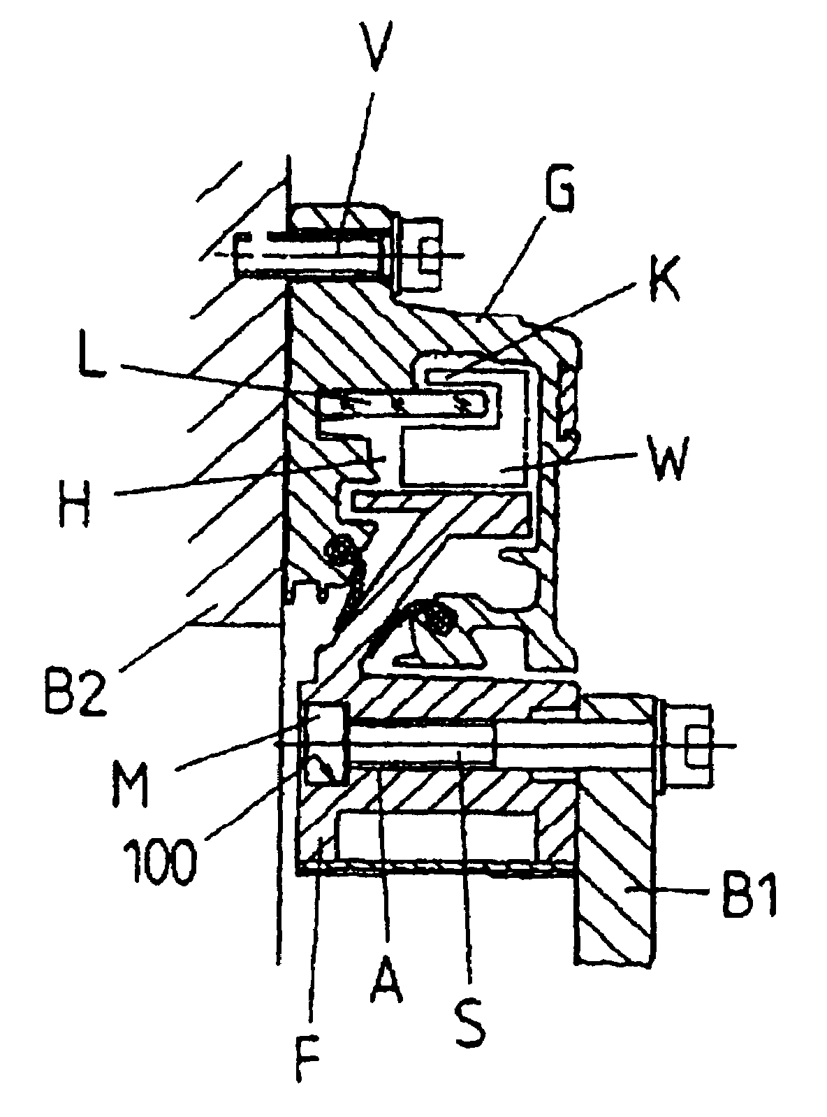
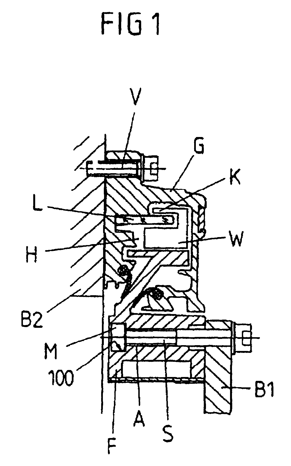
[0044]FIG. 1 shows a cross section through a position measuring system in the form of a linear measuring system, which is used for determining the relative position of two structural components B1, B2 of a machine tool, for example the machine bed and a structural tool group, which are movable in a linear direction with respect to each other.

[0045]The linear measuring system includes a position measuring device such as a linear scale L arranged in a hollow space H of a housing G extending in the longitudinal direction E of the scale L, as well as a second position measuring device such as a scanning unit that includes a scanning head K arranged on a scanning carnage W for scanning a measuring graduation applied to the scale L. The measuring graduation is arranged to be displaceable in relation to the linear scale L in the direction E of its extension in the hollow space H of the housing G and is connected with a mounting base F. The mounting base F on the one hand and the housing G ...


PUM


Abstract

A position measuring system for determining the position of a first structural component and a second structural component. The position measuring system includes a first support for receiving a first position measuring device, which is set up and provided for being fastened to the first structural component and a second support for receiving a second position measuring device, which is set up and provided for being fastened to the second structural component. The position measuring system further includes a first connector that fastens the first support to the first structural component and a second connector that fastens the second support to the second structural component, wherein the second connector includes a nut, with which a screw can be brought into engagement, wherein the nut is inserted into a recess of the second support. The position measuring system further includes a blocking element which, in an inserted state, works together with the nut in order to prevent a movement of the nut out of the recess in an axial direction, which is the direction of insertion of said screw into said nut, sufficiently far so that insertion of the screw into the nut is made possible.

Description

BACKGROUND OF THE INVENTION[0001]The present invention relates to a position measuring system for determining the position of two structural components which are movable in relation to each other.FIELD OF THE INVENTION[0002]Such a position measuring system includes a first support for receiving a position measuring device, such as a scale graduation, of the position measuring system, which is set up and provided for being fastened to one of the two structural components, as well as a second support for receiving a position measuring device, such as a scanning unit, of the position measuring system, which is set up and provided for being fastened to the other one of the two structural components which are movable with respect to each other, and furthermore connectors for fastening the two supports on the respectively assigned structural component. At least one of the connectors includes a nut and an associated screw, wherein the latter can be inserted into a recess of the support ass...

Claims


Application Information

Patent Timeline
IPC IPC(8): G01D5/347F16B41/00G01D11/30
CPCG01D11/305
Inventor HAGER, ANDREASFIEDLER, KARLTAUBER, JOHANN
Owner DR JOHANNES HEIDENHAIN GMBH
Learn More