
Mirror module

a mirror module and mirror technology, applied in the field of mirror modules, can solve the problems of not being able to optimize the shape of the scan engine, not having the cost and shock benefits of silicone materials, and not being able to use lim scan motors, etc., to achieve the effect of reducing the power required to drive the scan motor, low cost and small siz

Active Publication Date: 2007-10-16
SYMBOL TECH LLC
View PDF5 Cites 8 Cited by
  • Summary
  • Abstract
  • Description
  • Claims
  • Application Information

AI Technical Summary

Benefits of technology

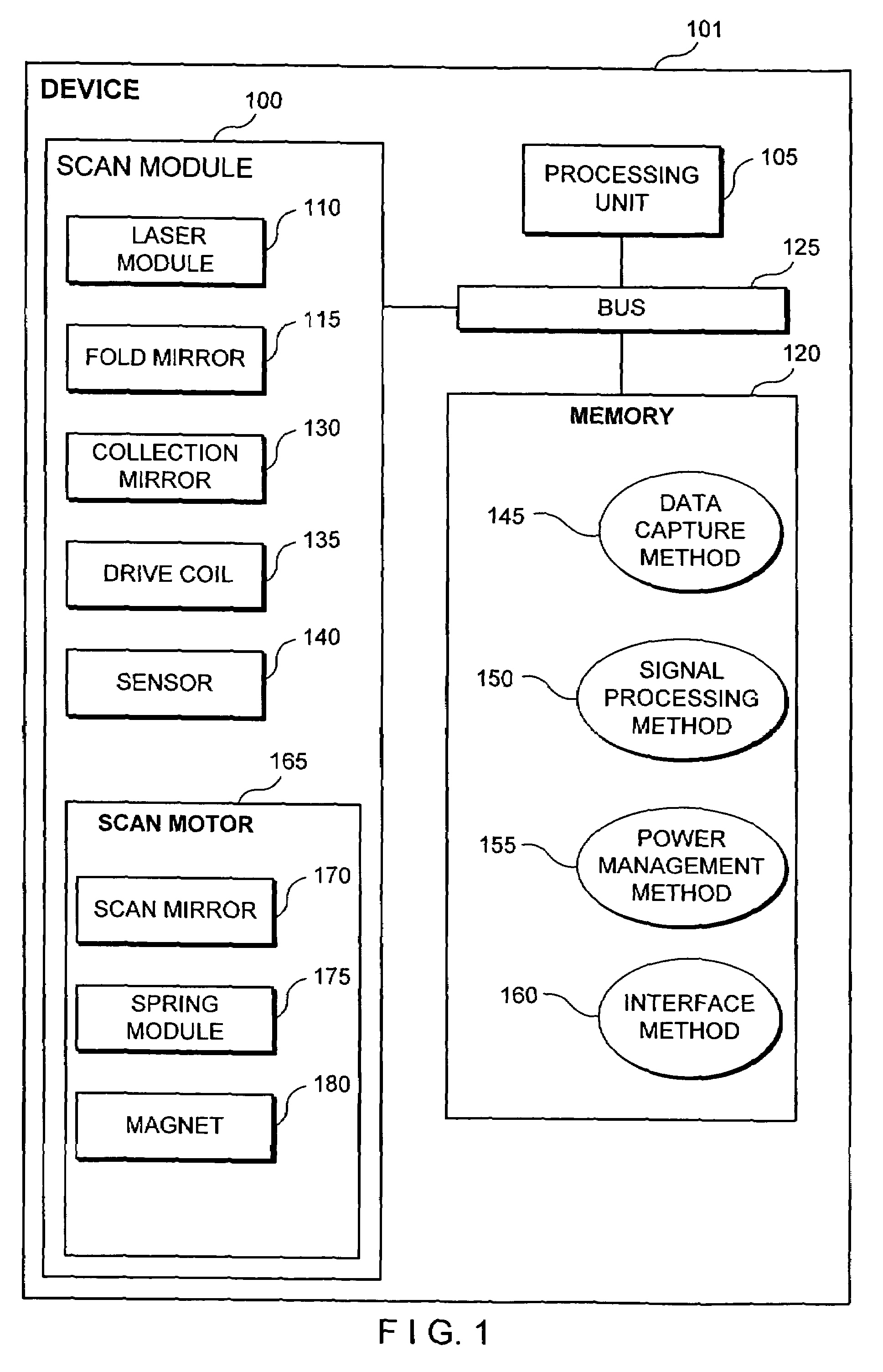
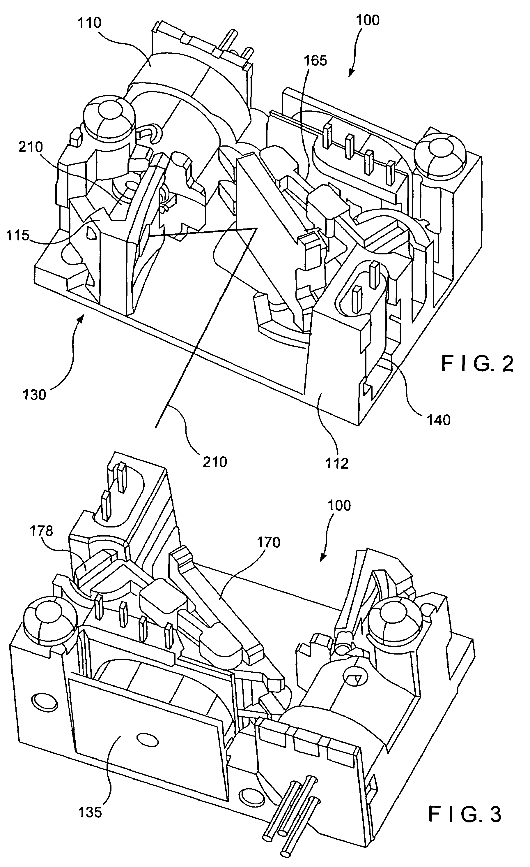
The invention described in this patent satisfies various needs by providing a scan module that includes a chassis, a drive coil, a scan motor, a laser, a mirror module, and a sensor. The scan motor includes a spring module, a magnet, and a reflective element, which can be made at low costs and with good shock protection. The scan module can be used in handheld scanners, portable computers, etc. The scan method involves driving the scan motor, directing a laser beam towards the reflective element, and creating a scan pattern. The scanner concentrates light from the dataform and reads the information displayed. The invention provides a more efficient and cost-effective solution for scanning and dataform reading.

Problems solved by technology

Since a retroreflective system uses a relatively large mirror, LIM scan motors have not been used since the drive voltages would be too high.
These materials do not have the cost and shock benefits of a material such as silicone.
In addition, it might not be possible to alter the shape of the scan engine to optimized internal volume, because an industry standard scan engine shape exists.
Because of the limited available volume, known small retroreflective scan engines might have sacrificed some collection area for other necessary features.
Unfortunately, this may not be desirable since industry standards may exists with respect to the shape of a scan engine.

Method used


Image

  • Mirror module
  • Mirror module
  • Mirror module

Examples


Embodiment Construction

[0030]There will now be shown and described in connection with the attached drawing figures several exemplary embodiments of methods and apparatus for providing a scan module.

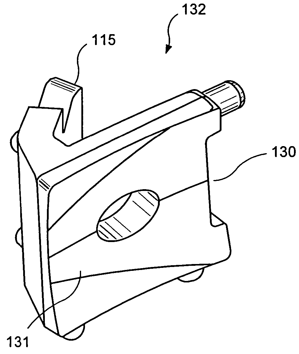
[0031]Shrinking scanning devices, such as handheld computers or mobile scanners comprise small scan modules for reading dataforms. Therefore, there is a desire to increase the performance of small scan modules, while reducing manufacturing costs. An exemplary scan module, implemented in accordance with the invention, that comprises a single piece mirror module has an increased collection area and a reduced manufacturing cost while maintaining an industry standard size.

[0032]Other embodiments of the invention comprise a scan motor with a molded assembly. It is beneficial to have non-retroreflective and retroreflective scan systems comprising a scan motor with excellent shock protection and a minimum number of parts to reduce the cost of the scan motor. For example, some technical specification require shock prot...


PUM


Abstract

A mirror module, comprising a collection mirror comprising an opening and a first reflective surface lying in a first plane, and a fold mirror coupled to said collection mirror, said fold mirror comprising a second reflective surface lying in a second plane, the second plane not being parallel to the first plane. In addition, said fold mirror may extend behind said collection mirror at an angle, wherein said angle is established so that a laser impinging on said fold mirror is reflected through said opening in said collection mirror.

Description

REFERENCE TO RELATED APPLICATIONS[0001]This application is a continuation-in-part of U.S. patent application Ser. No. 11 / 047,240, entitled, “Scan Motor”, filed Jan. 31, 2005 now U.S. Pat. No. 7,207,489. The specification of the above-identified application is incorporated herewith by reference.FIELD OF THE INVENTION[0002]The invention is directed to laser scanners and, more particularly to a scan module.BACKGROUND OF THE INVENTION[0003]There are numerous standards for encoding numeric and other information in visual form, such as the Universal Product Codes (UPC) and / or European Article Numbers (EAN). These numeric codes allow businesses to identify products and manufactures, maintain vast inventories, manage a wide variety of objects under a similar system and the like. The UPC and / or EAN of the product is printed, labeled, etched, or otherwise attached to the product as a dataform.[0004]Dataforms are any indicia that encode numeric and other information in visual form. For example...

Claims


Application Information

Patent Timeline
Patent Type & Authority Patents(United States)
IPC IPC(8): G06K7/10
CPCG06K7/10633G06K7/10702G06K7/10683G06K7/10653
Inventor SHEPARD, HOWARDDRZYMALA, MARKBARKAN, EDWARDZHANG, HENGGUREVICH, VLADIMIR
Owner SYMBOL TECH LLC
Learn More