EGR cooler purging apparatus and method

a technology of purging apparatus and cooler, which is applied in the direction of lighting and heating apparatus, machines/engines, transportation and packaging, etc., can solve the problems of reducing the percent-effectiveness of egr cooler, complicated and costly cooler design, and prone to condensation of compounds

Active Publication Date: 2007-10-16
INT ENGINE INTPROP CO LLC
View PDF8 Cites 45 Cited by
  • Summary
  • Abstract
  • Description
  • Claims
  • Application Information

AI Technical Summary

Problems solved by technology

The EGR cooler is especially prone to condensation of compounds in the exhaust gas passing through it.
Condensation inside the EGR cooler, or fouling, decreases the percent-effectiveness of the EGR cooler.
The incorporation of anti-fouling features, and the increased size of EGR coolers make cooler design complicated and costly.

Method used


Image

  • EGR cooler purging apparatus and method
  • EGR cooler purging apparatus and method
  • EGR cooler purging apparatus and method

Examples


Embodiment Construction

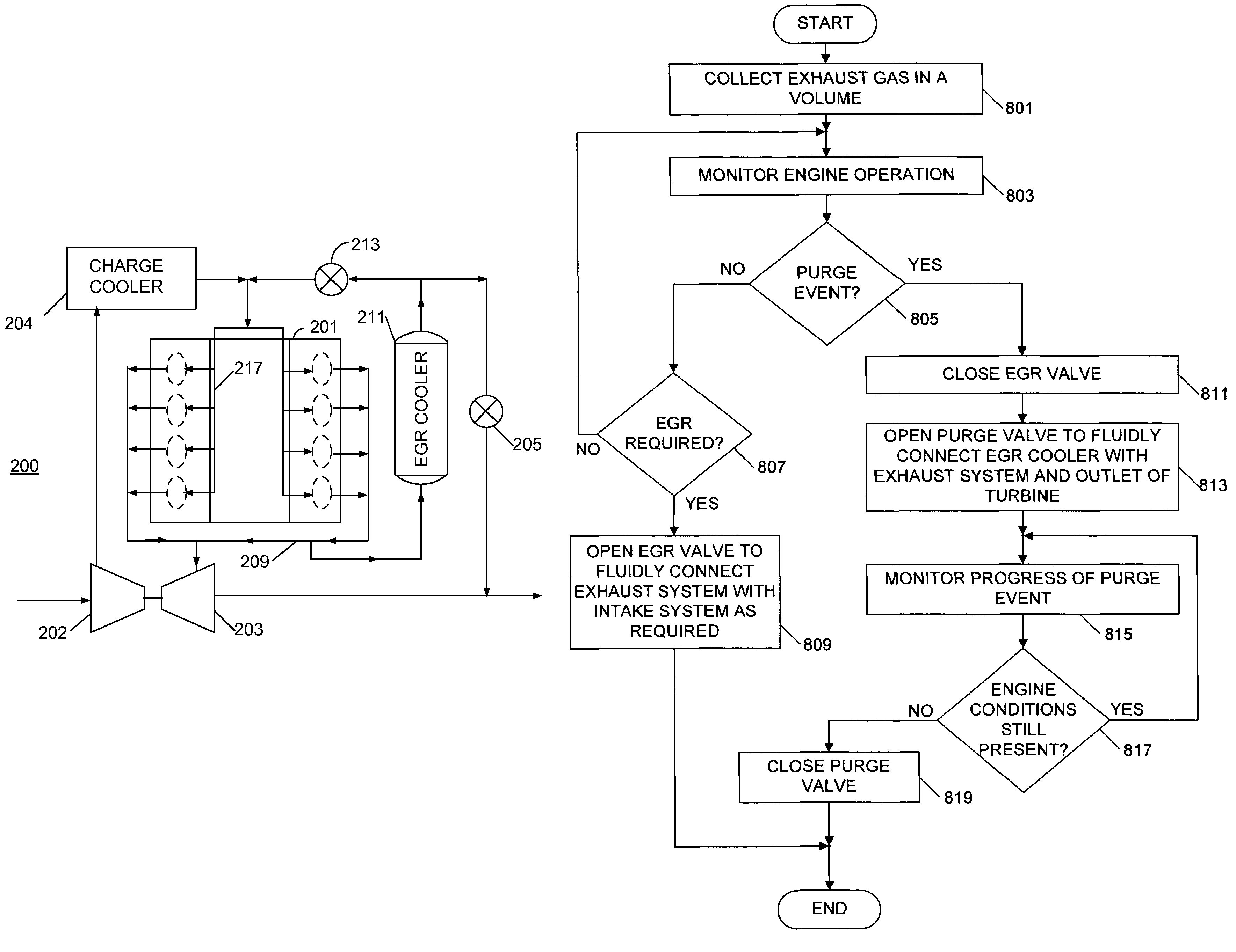
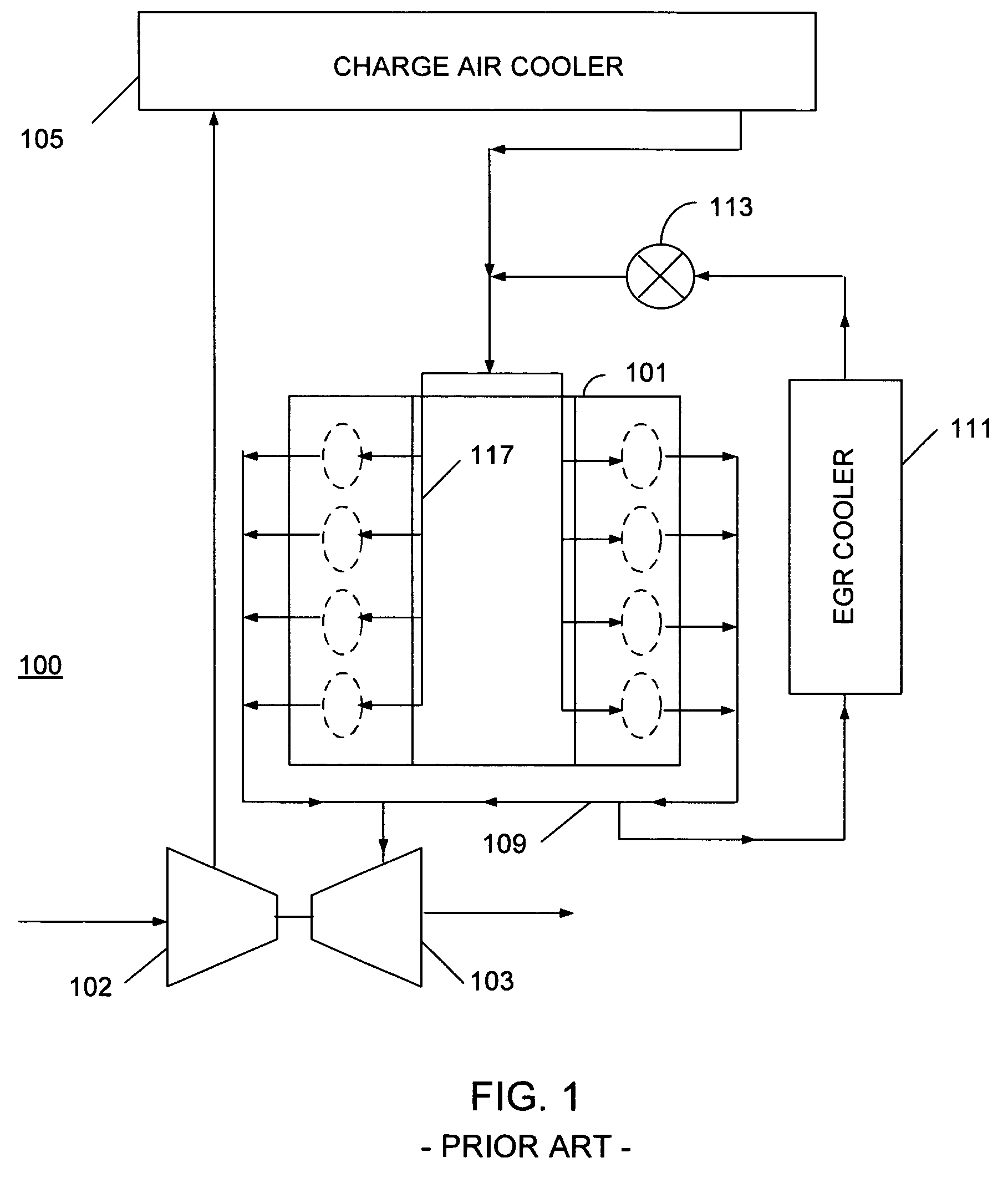
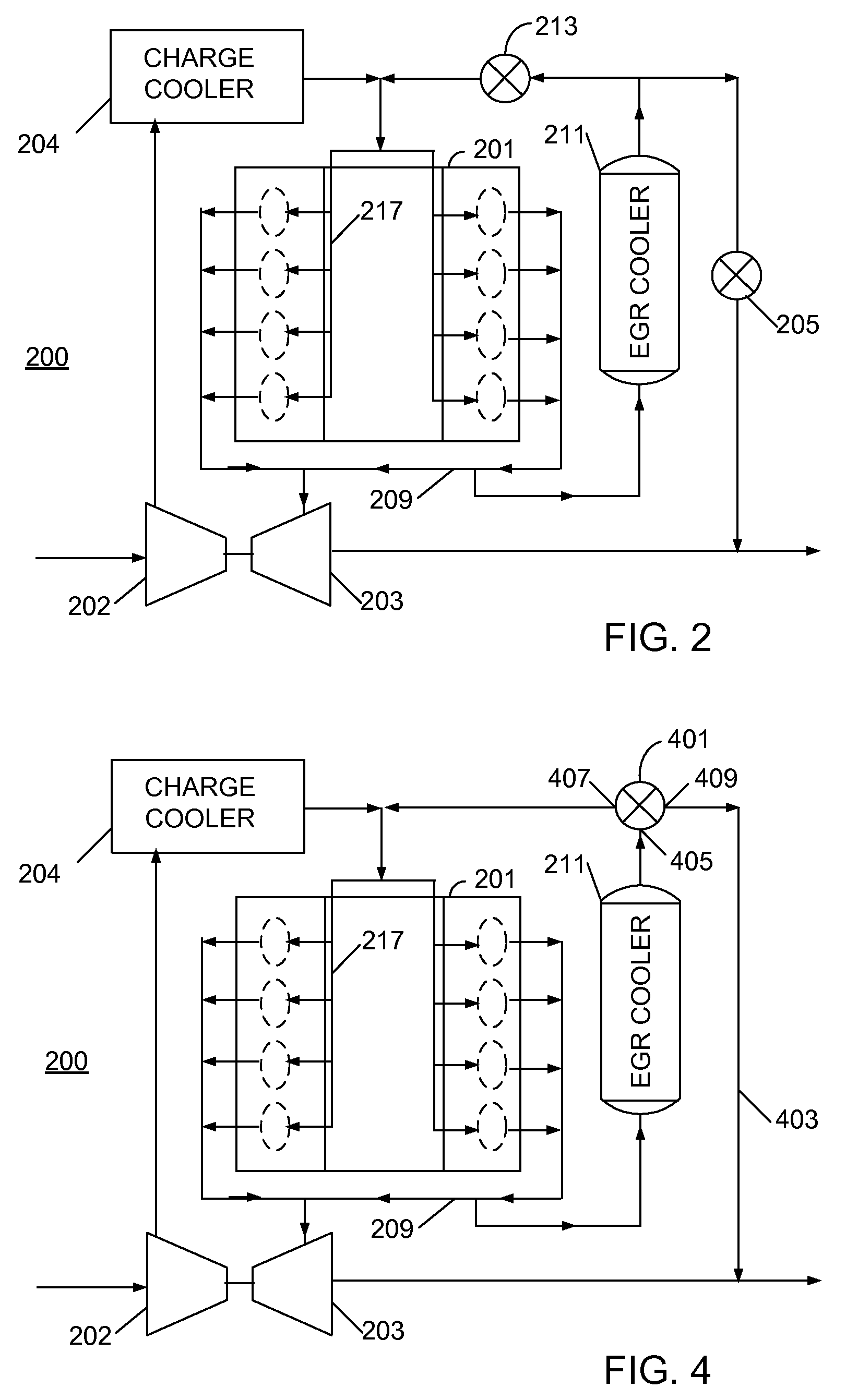
[0015]The following describes an apparatus for and method of cleaning or purging an EGR cooler in an internal combustion engine. The engine includes an EGR system having an EGR cooler fluidly communicating with the engine. A lock diagram of an engine having a high-pressure EGR system is shown in FIG. 1. A base engine 100 contains a plurality of cylinders housed in an engine block 101. A compressor 102 is connected to an air cleaner (not shown) and a turbine 103. An outlet of the compressor 101 is connected to a charge cooler 105, which in turn is connected to an intake system 117. The turbine 103 is connected to an exhaust system 109. The exhaust system 109 is connected to the engine block 101, and also connected to an EGR cooler 111. The EGR cooler 111 is connected to an EGR valve 113.

[0016]During engine operation, air from the air cleaner (not shown) enters the compressor 102. Exhaust gas from the engine block 101 enters the exhaust system 109. A portion of the exhaust gas in the ...


PUM


Abstract

An apparatus for an internal combustion engine (200) includes a base engine (201) having an intake system (217) and an exhaust system (209). A turbine (203) has an inlet in fluid communication with the exhaust system (209), and an outlet. A first exhaust gas recirculation (EGR) cooler (211) fluidly communicates with the intake system (217) and the exhaust system (209) of the engine (200). An EGR valve (213) is in fluid communication with the EGR cooler (211), and a purge valve (205) is in fluid communication with the EGR cooler (211) and the outlet of the turbine (203).

Description

FIELD OF THE INVENTION[0001]This invention relates to internal combustion engines, including but not limited to engines having cooled exhaust gas recirculation (EGR).BACKGROUND OF THE INVENTION[0002]Internal combustion engines with EGR, especially compression ignition engines, typically employ EGR coolers. EGR coolers are heat exchangers that typically use engine coolant to cool exhaust gas being recirculated into the intake system of the engine. Engine exhaust gas typically includes combustion by-products, such as unburned fuel, many types of hydrocarbon compounds, sulfur compounds, water, and so forth.[0003]Various compounds may condense and deposit on interior surfaces of engine components when exhaust gas is cooled. The EGR cooler is especially prone to condensation of compounds in the exhaust gas passing through it. The condensation is especially evident during cold ambient conditions, low exhaust gas temperatures, and / or low exhaust gas flow rates through the EGR cooler. Conde...

Claims


Application Information

Patent Timeline
Patent Type & Authority Patents(United States)
IPC IPC(8): F28G11/00
CPCF01N13/107F02B29/0406F02B37/00F02M26/05F02M26/23F02M26/44F02M26/50F02M26/71Y10T137/86879
Inventor LEW, MAE L.TERRY, WESLEY J.
Owner INT ENGINE INTPROP CO LLC
Why Eureka
Try Eureka