
Method of adaptive Walsh code allocation

a code allocation and adaptive technology, applied in the field of wireless communication, to achieve the effect of increasing voice capacity

Inactive Publication Date: 2007-10-09
LUCENT TECH INC
View PDF11 Cites 48 Cited by
  • Summary
  • Abstract
  • Description
  • Claims
  • Application Information

AI Technical Summary

Benefits of technology

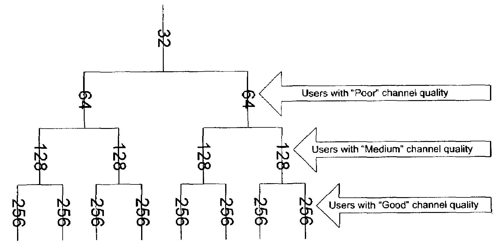
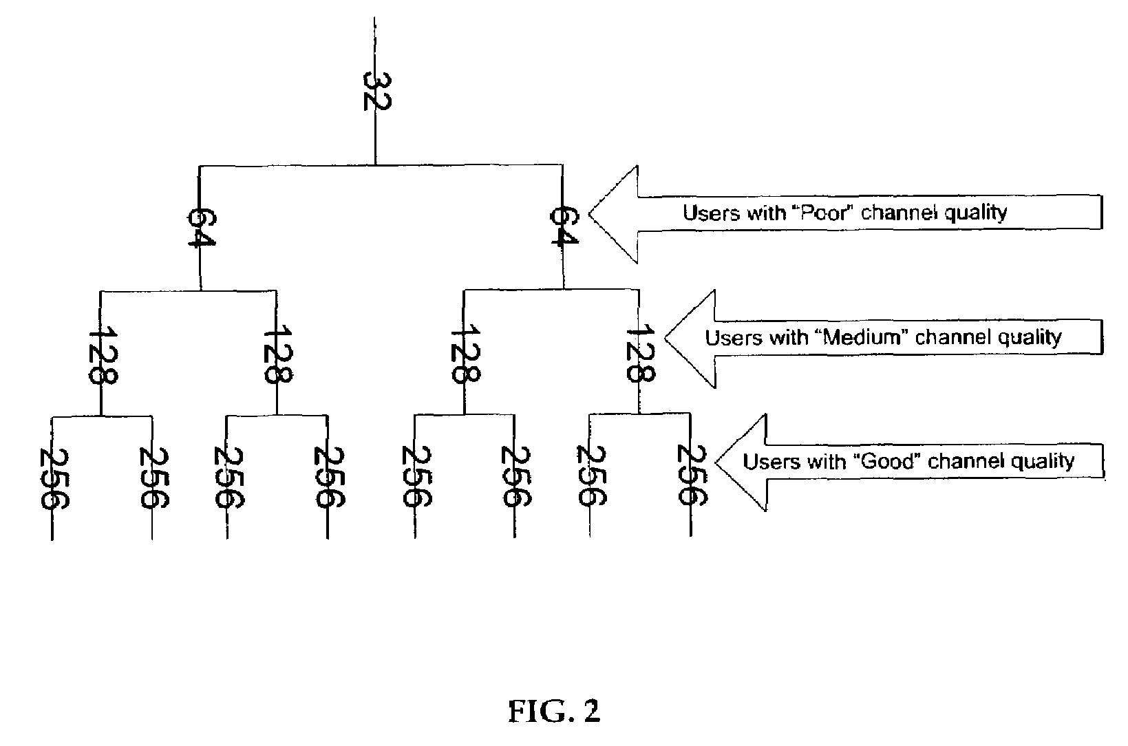
[0013]The present invention provides a method of increasing voice capacity on the downlink without unduly influencing power efficiency. More particularly, the present invention provides a method of adaptive Walsh code allocation, including, for example, determining a spreading factor for voice users in a wireless communication system in response to the quality of the channel conditions of each voice user. Once the spreading factor may be determined for each voice user, a Walsh code may be allocated to each user.

Problems solved by technology

Consequently, a tradeoff exists between the power efficiency of the base station based on the RC configuration employed and the length / number of spreading codes made available within each sector of a cell.

Method used


Image

  • Method of adaptive Walsh code allocation
  • Method of adaptive Walsh code allocation
  • Method of adaptive Walsh code allocation

Examples


Embodiment Construction

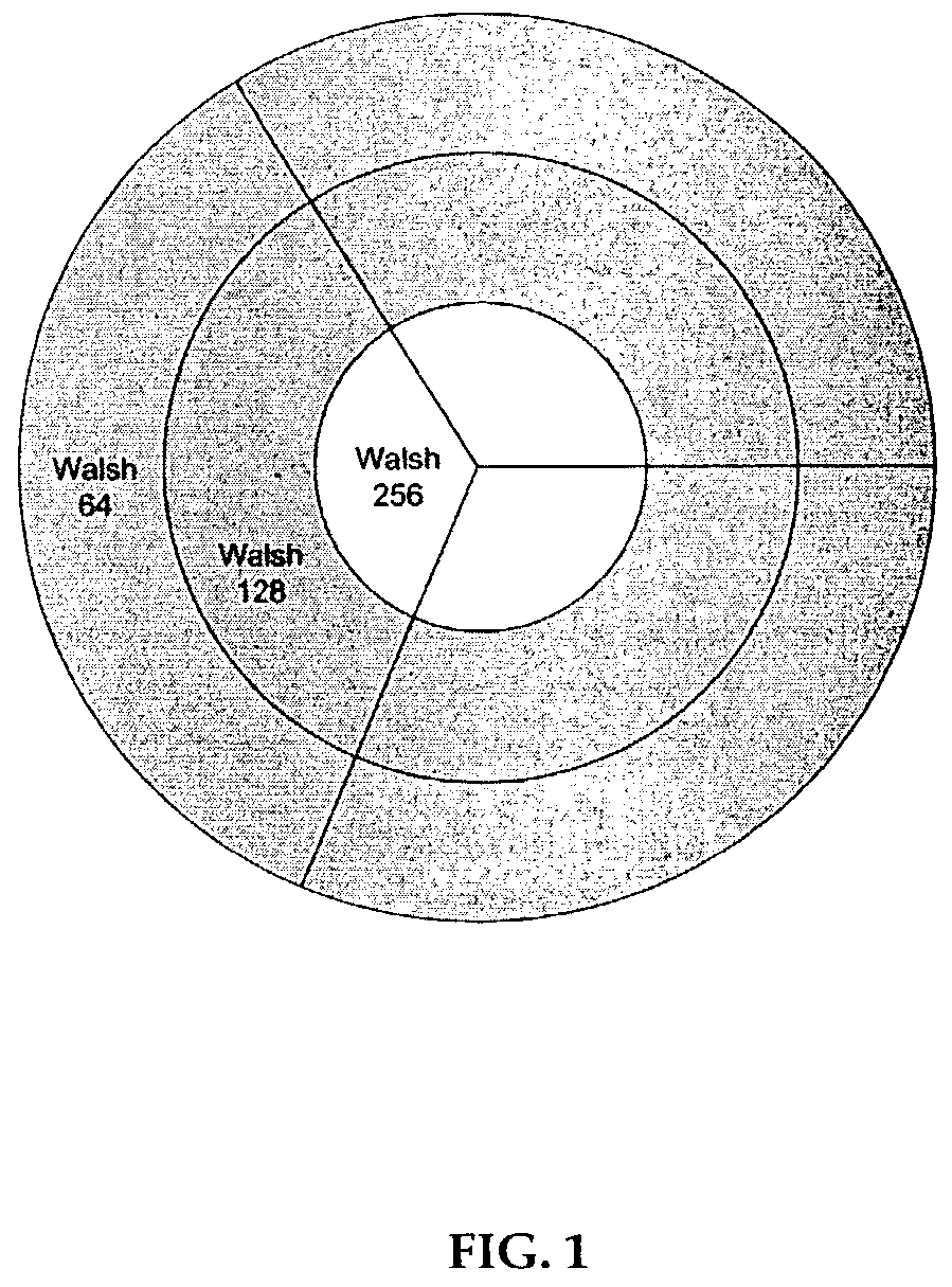
[0024]In current wireless systems employing the CDMA-based technology, orthogonal Walsh codes may be allocated for voice channels to different users. On the downlink, the total Walsh space may be shared between all the users on the carrier. In the uplink direction, all the Walsh space may be available to a given user. In general, Walsh codes with fixed spreading factor may be allocated to different users. For example, in a CDMA 2000 1x, a radio configuration 3 (“RC3”) uses a spreading factor of 64, while a radio configuration 4 (“RC4”) uses a spreading factor of 128 in the downlink. A Walsh code with a given spreading factor may be allocated at the time of call set up for the duration of the call of each user. For users in soft handoff (“SHO”), a Walsh code may be allocated from each sector in the active set. For the purposes of the present disclosure, an active set may consist of sector(s) with which each user may be in communication simultaneously.

[0025]The capacity of a CDMA syst...


PUM


Abstract

A method of adaptive Walsh code allocation in a wireless communication system. The method includes the step of each voice user transmitting quality condition signal, such as a pilot signal strength measurement to a corresponding base station. Upon receiving each quality condition signal, the method includes determining a spreading factor for each voice user in response to its quality condition signal. A Walsh code is thereafter allocated to each voice user in response to the determined corresponding spreading factor. Thus, for example, if the quality condition signal of a first voice user is relatively higher than the quality condition signal of a second voice user, the spreading factor allocated to the first voice user should be longer than the spreading factor of the second voice user.

Description

BACKGROUND OF THE INVENTION[0001]I. Field of the Invention[0002]The present invention relates to telecommunications, and more particularly, to wireless communications.[0003]II. Description of the Related Art[0004]Wireless communications systems provide wireless service to a number of wireless or mobile units situated within a geographic region. The geographic region supported by a wireless communications system is divided into spatially distinct areas commonly referred to as “cells.” Each cell, ideally, may be represented by a hexagon in a honeycomb pattern. In practice, however, each cell may have an irregular shape, depending on various factors including the topography of the terrain surrounding the cell. Moreover, each cell is further broken into two or more sectors. Each cell is commonly divided into three sectors, each having a range of 120 degrees, for example.[0005]A conventional cellular system comprises a number of cell sites or base stations geographically distributed to s...

Claims


Application Information

Patent Timeline
Patent Type & Authority Patents(United States)
IPC IPC(8): H04L27/30H04B1/707H04J11/00H04J13/02H04W72/54
CPCH04J13/0048H04J13/18H04W72/08Y02D30/70H04W72/54
Inventor KHAN, FAROOQ ULLAH
Owner LUCENT TECH INC
Learn More