
Ocean current power generator

Inactive Publication Date: 2007-10-09
BOSLEY KENNETH RANDALL
View PDF37 Cites 37 Cited by
  • Summary
  • Abstract
  • Description
  • Claims
  • Application Information

AI Technical Summary

Benefits of technology

[0031]The present invention is an apparatus and method for extracting municipally significant quantities of electrical power from ocean currents, without the mechanical losses typically found in most underwater generators, without the transfer of electricity from rotating to non-rotating components, and without the maintenance challenges found in most approaches. In the preferred embodiments, a large-diameter marine screw (or “impeller”) is harnessed to two generators linked in series and split between the rotating (“rotor”) and non-rotating (“stator”) parts of the hydro-turbine, the axis of which is located parallel to a prevailing ocean current. Optionally, the hydro-turbine is enclosed in a shroud designed to accelerate the current through a more constricted area.
[0034]Accordingly, it is a principal object of the invention to provide a means of reliably generating significant quantities of electrical energy from the kinetic energy of ocean currents.
[0035]It is another object of the invention to maximize the amount of electricity generated from ocean currents, by generating electricity as directly as possible, without mechanical losses due to gears and seals, or electrical losses due to brushes or inductive transferal technologies. By using the split-series double-generator set, all transfer of electricity from rotating to non-rotating parts is eliminated, thus avoiding the mechanical losses common to other generating technologies.
[0036]It is a further object of the invention to eliminate several categories of maintenance problems, thus reducing the operating cost and increasing the reliability of the generator. By using the split-series double-generator set, all transfer of electricity from rotating to non-rotating parts is eliminated, along with pressure hulls, high-speed gear sets, brushes, seals, and other mechanical and electrical sources of power loss, maintenance difficulties, and hazards to marine life.
[0038]It is an object of the invention to provide improved elements and arrangements thereof in an apparatus for the purposes described which is inexpensive, dependable and fully effective in accomplishing its intended purposes.

Problems solved by technology

Various schemes have been used to solve these problems, but they have all entailed significant degradation to operating efficiency, maintenance problems, durability limitations, and unacceptable reductions in the portion of the total energy extracted from the ocean's current.

Method used


Image

  • Ocean current power generator
  • Ocean current power generator
  • Ocean current power generator

Examples


Embodiment Construction

[0049]The present invention is a method and apparatus for generating power from fluid currents, having four sets of electromagnetic coils.

[0050]FIG. 1 is a front elevational view of the first preferred embodiment of the invention, showing the turbine 10, comprising the impeller 12, which is retained within the frame 14, and rotates on shaft 16. When a water current flows through the turbine, the impeller rotates, while the frame and shaft remain stationary. The pressure of water against blades 18 causes the impeller to turn. Also shown in FIG. 1 are the first set of electromagnetic coils 20 and the fourth set of electromagnetic coils 26.

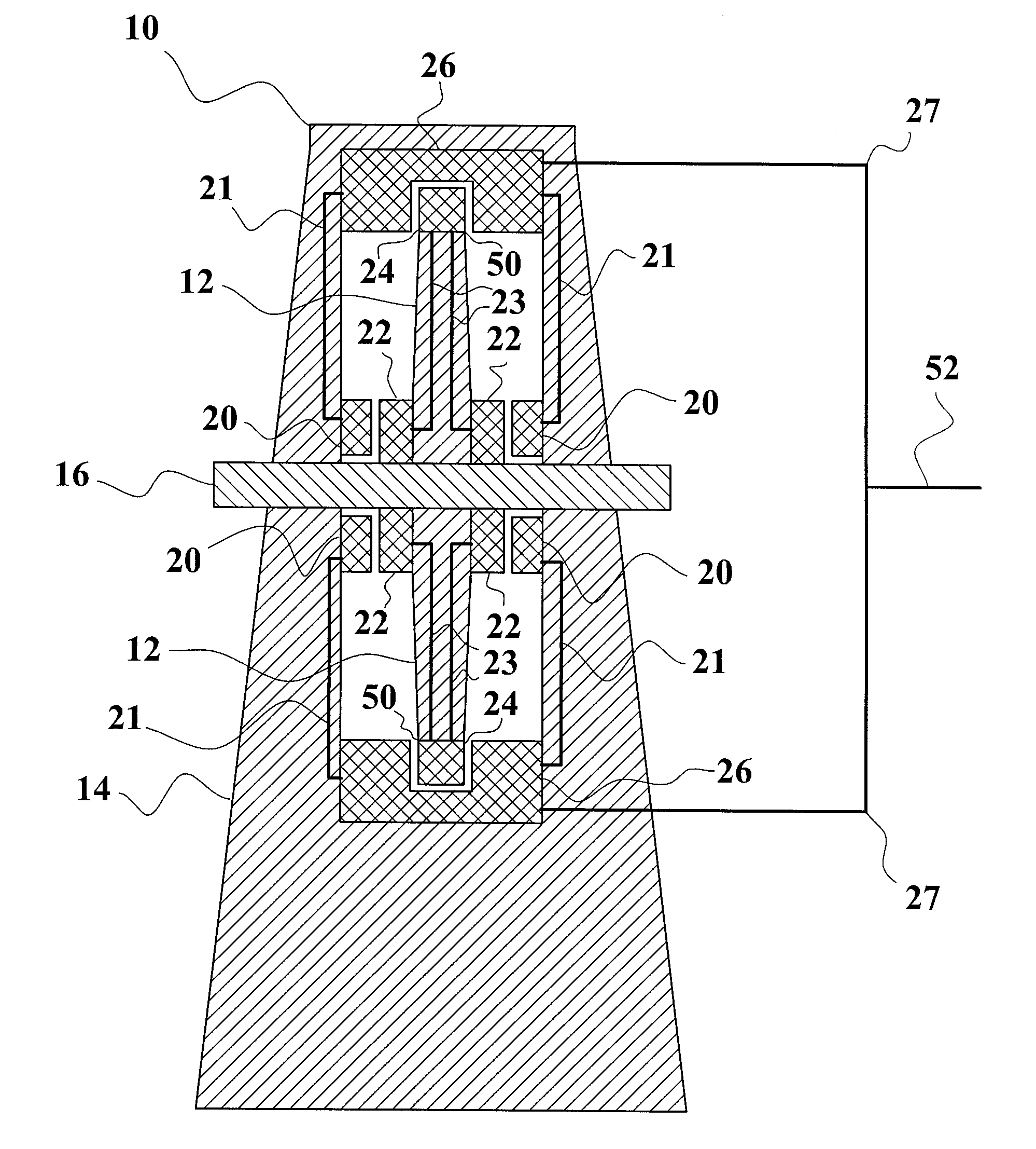
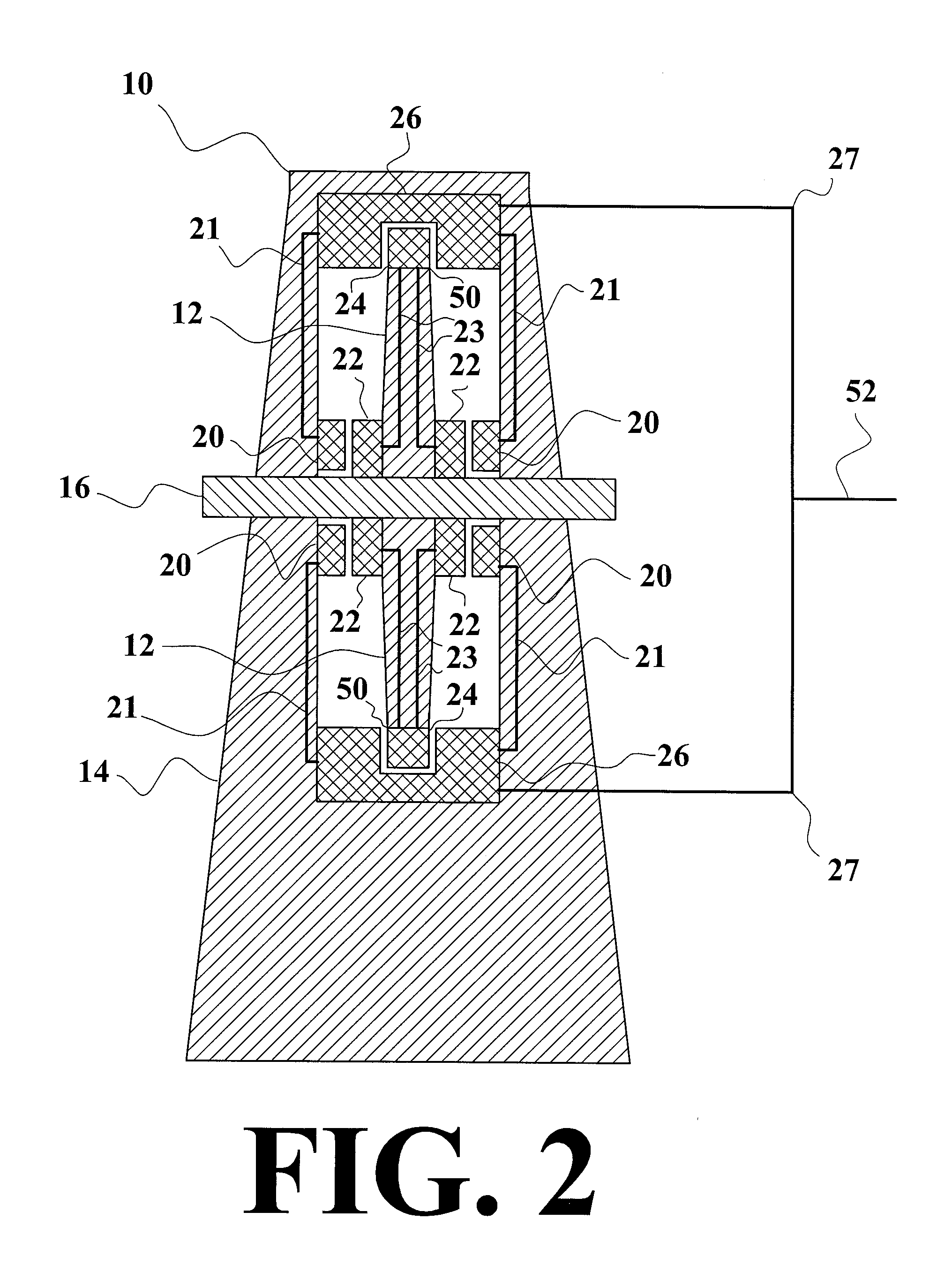
[0051]FIG. 2 is a sectional view of the first preferred embodiment of the invention drawn along line 2-2 of FIG. 1, showing the first set of electromagnetic coils 20, which are attached to the shaft 16 (or to the frame 14 adjacent to the shaft) and thus are stationary, the second set of electromagnetic coils 22, which are near the shaft but are attac...


PUM


Abstract

An apparatus and method for generating electricity from the movement of seawater in ocean currents. An impeller is set within a stationary frame. The impeller rotates around a non-moving shaft. There are four sets of electromagnetic coils, two of which are stationary, and two of which rotate with the impeller. The first set of coils is stationary. The second and third sets of coils rotate with the impeller. The second set of coils moves past the first set, generating an electric current which is used to energize the third set of coils. The fourth set of coils is also stationary. The third set of coils moves past the fourth set, generating another electric current, part of which is fed back to the first set of coils until they are brought to a maximum operating electro-magnetic field density, and part of which is transmitted externally to supply electric power on shore.

Description

BACKGROUND OF THE INVENTION[0001]1: Field of the invention[0002]The present invention relates to the generation of electrical power, preferably using large hydro-turbines submerged in powerful ocean currents, but it may be adapted to tidal or weaker current applications.[0003]2: Description of the Prior Art[0004]There is an increasing need for greater amounts of electrical power, and an increasing desire to minimize pollution of the environment caused by generating the electrical power. Consequently, several imaginative techniques have been devised for harvesting power from the large-scale motions of seawater. E.g., the Gulf Stream along Florida's east coast transfers approximately 517 gigawatts of power northward, or about 4.5 petawatt / hours each and every year. Ocean currents are driven by heat differentials on the earth due to uneven insolation. The present invention addresses the difficulty in extracting usable portions of this low-density power in an economical way.[0005]U.S. P...

Claims


Application Information

Patent Timeline
IPC IPC(8): F03B13/00F03D9/00
CPCF03B3/126F03B11/02F03B13/10F03B13/264F05B2240/14Y02E10/725F05B2250/5011F05B2280/5008Y02E10/223Y02E10/226Y02E10/28F05B2240/97Y02E10/20Y02E10/30Y02E10/72
Inventor BOSLEY, KENNETH RANDALL
Owner BOSLEY KENNETH RANDALL
Learn More