Damper device for a piston pump

a technology of damper and piston pump, which is applied in the direction of machines/engines, positive displacement liquid engines, pulse equalisation, etc., can solve the problems of time loss and product loss, the above-described damper will achieve far too short an operational running time, and cannot normally be cleaned in the cip system of the dairy plan

Inactive Publication Date: 2007-10-09
TETRA LAVAL HLDG & FINANCE SA
View PDF8 Cites 16 Cited by
  • Summary
  • Abstract
  • Description
  • Claims
  • Application Information

AI Technical Summary

Benefits of technology

[0014]Yet a further object of the present invention is that the dampers may be supplied with fresh air during operation, which contributes in fewer production stoppages and reduced product losses caused by the dampers.
[0015]Still a further object of the present invention is that the damper may, in a simple manner, be adapted to aseptic applications.SUMMARY OF THE INVENTION

Problems solved by technology

In most practical applications, the above-described type of damper is efficient from the point of view of damping, but cannot normally be cleaned in the CIP system of the dairy plant (Cleaning In Place).
Nor is such a damper suitable for aseptic applications, since the upright tube is difficult to sterilize in connection with the sterilization of the remaining equipment.
It has hitherto not been possible to replenish air while the plant is in operation, but it has instead been necessary to stop production, which has entailed both time losses and losses of product.
Requirements on higher output capacities and longer running times, for example within the food industry, as well as the utilisation of higher pressure on the pressure side of the pump entail that the above-described dampers will attain far too short an operational running time.
The air in the upright tubes is consumed rapidly and production stoppages become necessary.
These dampers are expensive in operation, since the membrane often needs to be replaced.
However, this entails not inconsiderable product losses.
Specialist inlet dampers provided with an external steam hat involve many parts which are difficult to clean and which may cause problems with regard to sterility in aseptic plants.
Another type of damper is the resonator type which suffers from the drawback of being difficult to clean and thereby not suitable for food applications.

Method used


Image

  • Damper device for a piston pump
  • Damper device for a piston pump
  • Damper device for a piston pump

Examples


Embodiment Construction

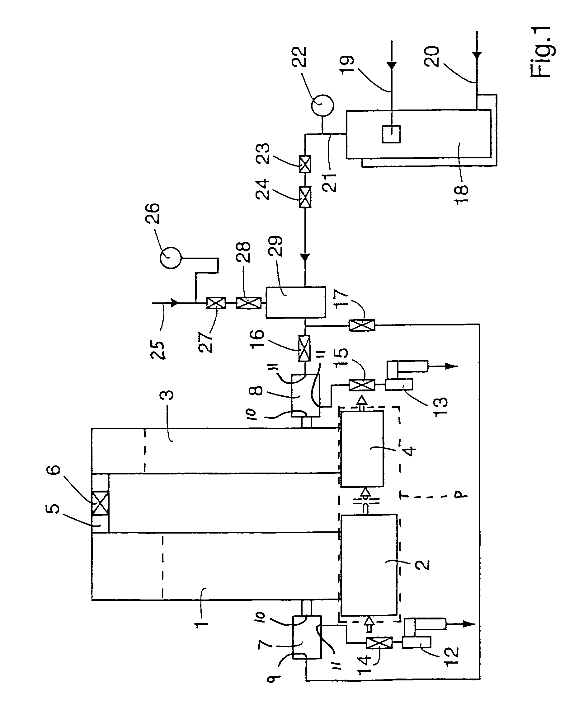
[0022]Fig 1 is a schematic illustration of a damper device for a piston pump or a homogenizer (the piston pump or homogenizer is not shown on the Drawings) according to the present invention. The damper device includes a partly air-filled upright tube 1 which is placed on a tube 2 constituting the inlet of the piston pump. The piston pump is generally designated in FIG. 1 as P. The damper device also includes a partly air-filled upright tube 3 which is placed on a tube 4 constituting the outlet of the piston pump. Normally, the damper device is integral with the homogenizer or the piston pump.

[0023]The two upright tubes 1 and 3 are interconnected to one another by means of a tube 5 on which a shut-off valve 6 is disposed. The shut-off valve 6 is mounted so that it may serve partly as a safety valve and partly as a valve which may open a communication between the two upright tubes 1, 3. If a stoppage were to occur in the outlet tube 4 of the piston pump, the shut-off valve 6 opens an...


PUM


Abstract

The invention relates to a damper device for a piston pump. The device includes a partly air-filled, upright tube placed on the inlet conduit of the piston pump, and a partly air-filled, upright tube placed on the outlet conduit of the piston pump. The two upright tubes are interconnected with each other by means of a tube on which a shut-off valve is disposed. Each of the upright tubes is connected to a blower valve, respectively. Both of the blower valves are connected to a common compressed air source. The damper device may be adapted in a simple manner for aseptic operation and / or elevated product pressure.

Description

FIELD OF THE INVENTION[0001]The present invention relates to a damper device for a piston pump comprising a partly air-filled, upright tube placed on the inlet of the piston pump, and a partly air-filled upright tube placed on the outlet of the piston pump, both upright tubes being mutually interconnected by means of a shut-off valve.BACKGROUND OF THE INVENTION[0002]A piston pump is a high pressure pump of the positive displacement variety which substantially consists of a powerful electric motor, transmission mechanism and crank mechanism, as well as a pump assembly with a pump block, valves and a number of plungers or pistons. The rotary movement from the electric motor is converted by means of the transmission mechanism into the reciprocating movement of the pistons.[0003]One common field of practical application for a high pressure pump of the piston type is in a homogenizer. In those cases where the high pressure pump is employed as a homogenizer, the pump block is supplemented...

Claims


Application Information

Patent Timeline
Patent Type & Authority Patents(United States)
IPC IPC(8): F04B11/00
CPCF04B11/0025
Inventor MALMBERG, ROLFOLSSON, TORSTENPERSSON, LARS-GORAN
Owner TETRA LAVAL HLDG & FINANCE SA
Why Eureka
Try Eureka