
Timing mechanism for a switchable two-step roller finger follower

a timing mechanism and roller finger follower technology, applied in mechanical equipment, machines/engines, valve drives, etc., can solve the problems of insufficient engagement to complete the full valve event, rff cannot function properly, and the lock pin may only be partially engaged

Inactive Publication Date: 2007-10-09
DELPHI TECH IP LTD
View PDF11 Cites 9 Cited by
  • Summary
  • Abstract
  • Description
  • Claims
  • Application Information

AI Technical Summary

Problems solved by technology

In prior art RFFs, a known problem exists in that the lock pin may be only partially engaged with the high-lift follower portion of the RFF when a high-lift valve event begins.
In some instances, there is enough engagement to begin to open the valve but not enough engagement to complete the full valve event.
Premature lock pin ejection is highly undesirable because a) the intended valve and engine event is frustrated, resulting in improper engine operation; b) the extreme shock produced in associated engine components may cause damage; and c) repeated ejections can damage the lock pin and the high-lift follower portion such that the RFF cannot function properly and must be replaced.

Method used


Image

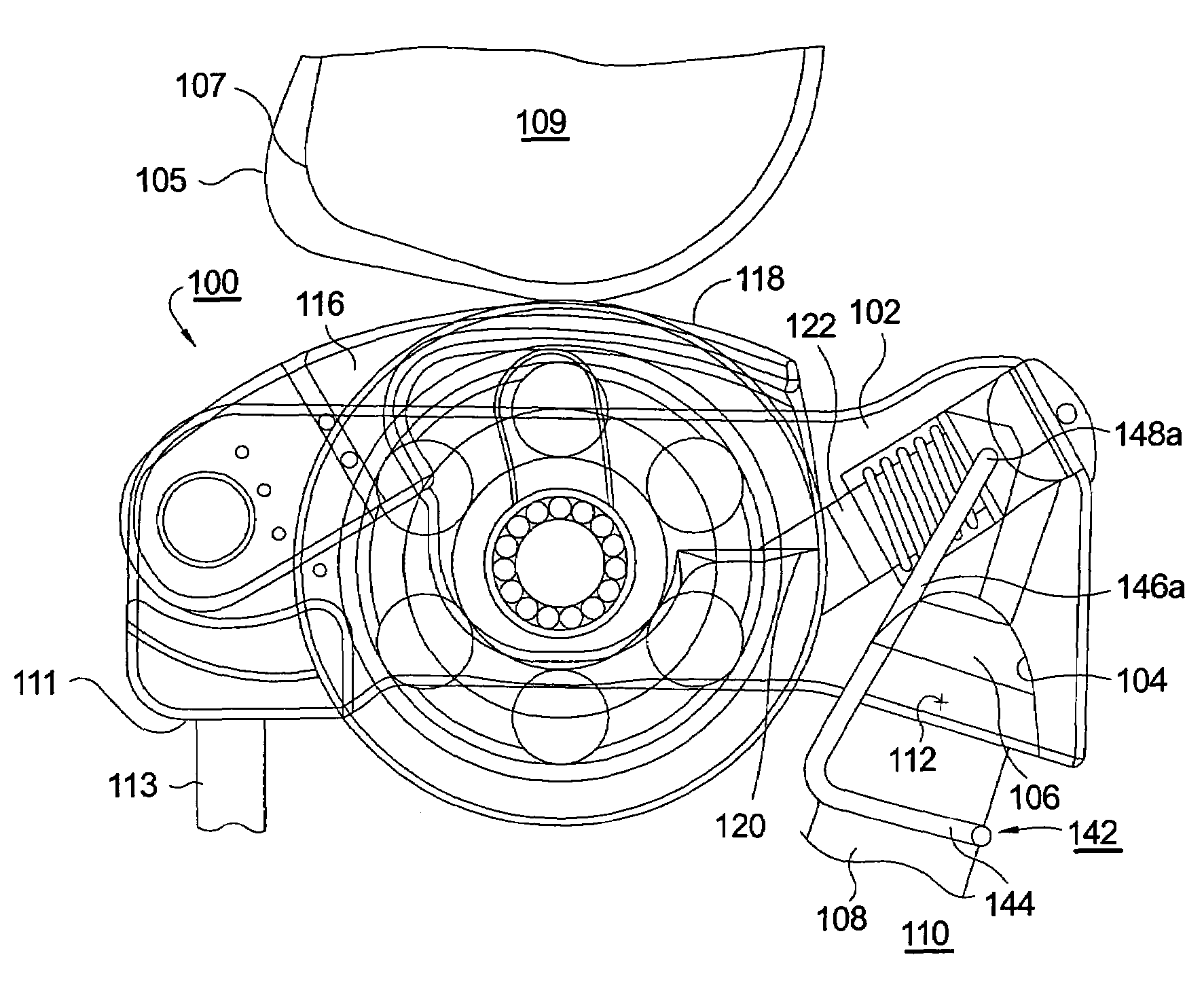
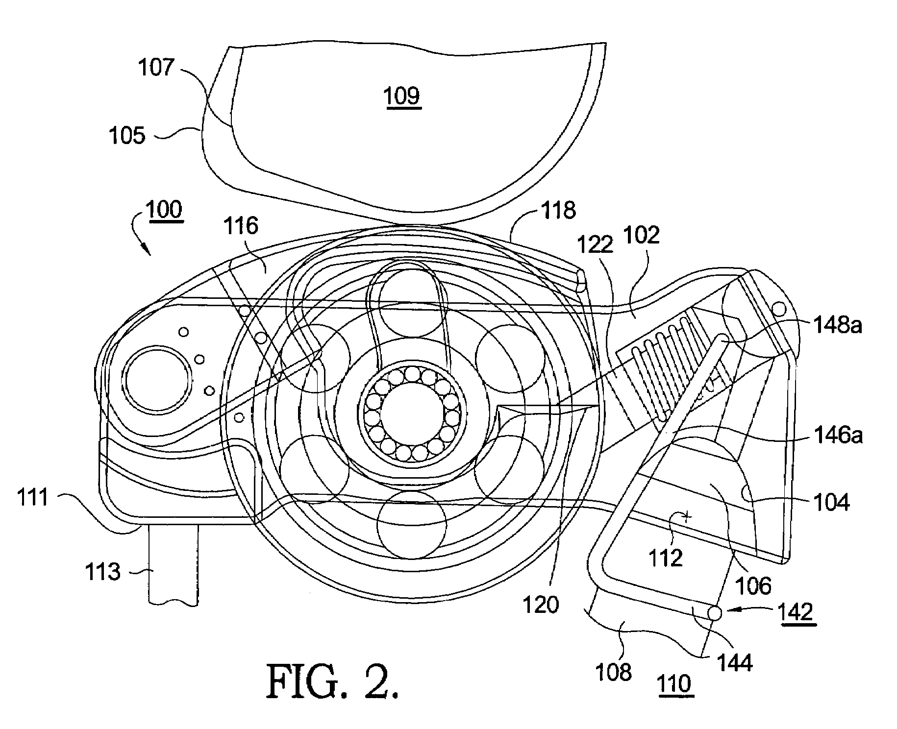
  • Timing mechanism for a switchable two-step roller finger follower
  • Timing mechanism for a switchable two-step roller finger follower
  • Timing mechanism for a switchable two-step roller finger follower

Examples


Embodiment Construction

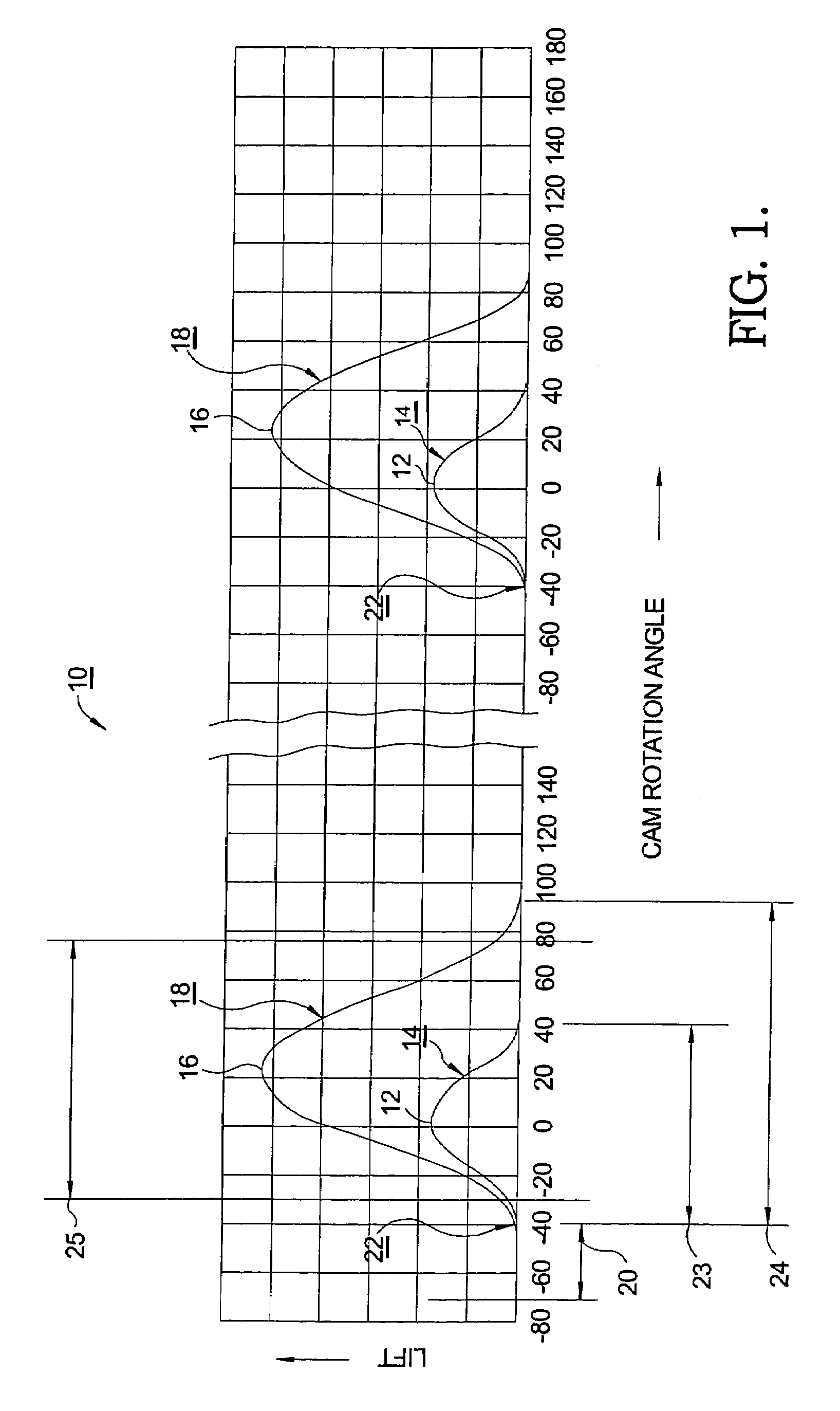
[0016]Referring to FIG. 1, a graph 10 shows exemplary valve lift profiles as a function of cam rotation angle in an internal combustion engine for two revolutions of the cam. The peak lift 12 for a low-lift valve event 14 is arbitrarily defined herein as 0° cam rotation angle. In the present example, the peak lift 16 for a high-lift valve event 18 is about 21° after low-lift peak 12. The duration of low lift event 14, shown as segment 23 in FIG. 1, is from before about −30 degrees to after about +30 degrees. The duration of high-lift event 18, shown as segment 24 in FIG. 1, is from before about −30 degrees to after about +88 degrees. A two-step roller finger follower is capable of selectively providing either low-lift event 14 or high-lift event 18 in response to a hydraulic signal provided via an electronic engine control module, as is well known in the prior art.

[0017]As described above, a problem in prior art RFFs is that the cam rotation angle at which the RFF is commanded to lo...


PUM


Abstract

A two-step roller finger follower having a movable high-lift portion and a low-lift portion. A lock pin mechanism in the low-lift portion includes a lock pin that may be driven hydraulically into latched engagement with the high-lift portion. The lock pin assembly comprises a lock pin and a separable switching pin. A blocking clip mountable on the associated hydraulic lash adjuster includes first and second ends that extend into a switching pin locking groove to block axial motion thereof. A ramp on the follower body mates with a ramp on the blocking clip such that oscillatory motion of the follower engages and disengages the blocking pin from the locking groove. The clip unblocks the switching pin at only those times in the camshaft rotational cycle when complete locking and unlocking is assured, and ending well before the beginning of the next valve lift event.

Description

TECHNICAL FIELD[0001]The present invention relates to roller finger followers for actuating the valves of internal combustion engines; more particularly, to two-step roller finger followers for controllably activating and deactivating engine valves between high-lift and low-lift modes; and most particularly, to a two-step roller finger follower having a timing mechanism governing locking and unlocking action of a lock pin to prevent partial pin engagement and consequent premature pin ejection during a high-lift valve event.BACKGROUND OF THE INVENTION[0002]Two-step roller finger followers (RFF) for controllably activating and deactivating compression valves in a variable valve activation train in an internal combustion engines are well known. An RFF extends between a hydraulic lash adjuster (HLA) and the stem of a valve. Engagement of the RFF with a cam lobe of an engine camshaft causes the RFF to be pivoted about the HLA and thereby to depress the valve stem, opening the valve.[0003...

Claims


Application Information

Patent Timeline
Patent Type & Authority Patents(United States)
IPC IPC(8): F01L1/34
CPCF01L1/185F01L13/0005F01L13/0036F01L1/14Y10T74/2107F01L2105/00Y10T74/2102F01L2001/186F01L2305/00
Inventor FERNANDEZ, HERMES A.LIPINSKI, ANDREW J.
Owner DELPHI TECH IP LTD
Learn More