
Push planning for unserviceable parts to facilitate repair planning in a repair network

a technology of unserviceable parts and repair planning, applied in the direction of multi-programming arrangements, electric programme control, instruments, etc., to achieve the effect of reducing the disadvantages and problems of previous repair planning techniques or eliminating them

Active Publication Date: 2007-10-02
BLUE YONDER GRP INC
View PDF12 Cites 14 Cited by
  • Summary
  • Abstract
  • Description
  • Claims
  • Application Information

AI Technical Summary

Benefits of technology

[0005]According to the present invention, disadvantages and problems associated with previous repair planning techniques may be reduced or eliminated.
[0007]Particular embodiments of the present invention may provide one or more technical advantages. For example, particular embodiments may provide on-demand repair planning, for each of a number of time periods in a planning horizon, based on one or more demands for parts at one or more future times at one or more repair locations. In particular embodiments, a repair location at which the demand exists may be one of multiple repair locations in a multi-level repair network. In particular embodiments, a part may be repaired at a repair location at a latest time that allows the part to be available to help satisfy a demand at a repair location at which the demand exists. In particular embodiments, a part may be moved between repair locations at a latest time that allows the part to be available to help satisfy a demand at a repair location at which the demand exists. In particular embodiments, determining a latest time at which a part can be repaired at a repair location or moved between repair locations may reflect one or more disposition times associated with inspections of the part at one or more repair locations, repair lead times associated with repair of the part at a repair location, one or more move lead times associated with movement of the part between repair locations, and any other appropriate time constraints. In particular embodiments, the present invention allows parts to be repaired (and moved where appropriate) in a “just-in-time” manner, these decisions being made for each of a number of time periods in a planning horizon, each part being repaired (and moved where appropriate) only when needed to satisfy a demand and as late in time as is possible to satisfy the demand. In particular embodiments, the generation of planned repair and move orders may also help integrate planning with execution.
[0008]In particular embodiments, the ability to provide on-demand repair planning may minimize undesirable costs associated with broken or otherwise unusable parts, improving the cost-efficiency of the supply chain and increasing overall profitability. For example, in particular embodiments, it may be desirable to repair a part as late in time as possible in order to delay commitment of scarce capital or other resources to the repair process and to make these capital and other resources available for other business activities. As a more particular example, delaying repair may help prevent adding value to a part through repair only to have the repaired part “sit on the shelf” due to a lack of demand. As another more particular example, delaying repair may help minimize losses where the repaired part is likely to suffer attrition due to shelf-life constraints or obsolescence.

Problems solved by technology

As a more particular example, delaying repair may help prevent adding value to a part through repair only to have the repaired part “sit on the shelf” due to a lack of demand.

Method used


Image

  • Push planning for unserviceable parts to facilitate repair planning in a repair network
  • Push planning for unserviceable parts to facilitate repair planning in a repair network
  • Push planning for unserviceable parts to facilitate repair planning in a repair network

Examples


Embodiment Construction

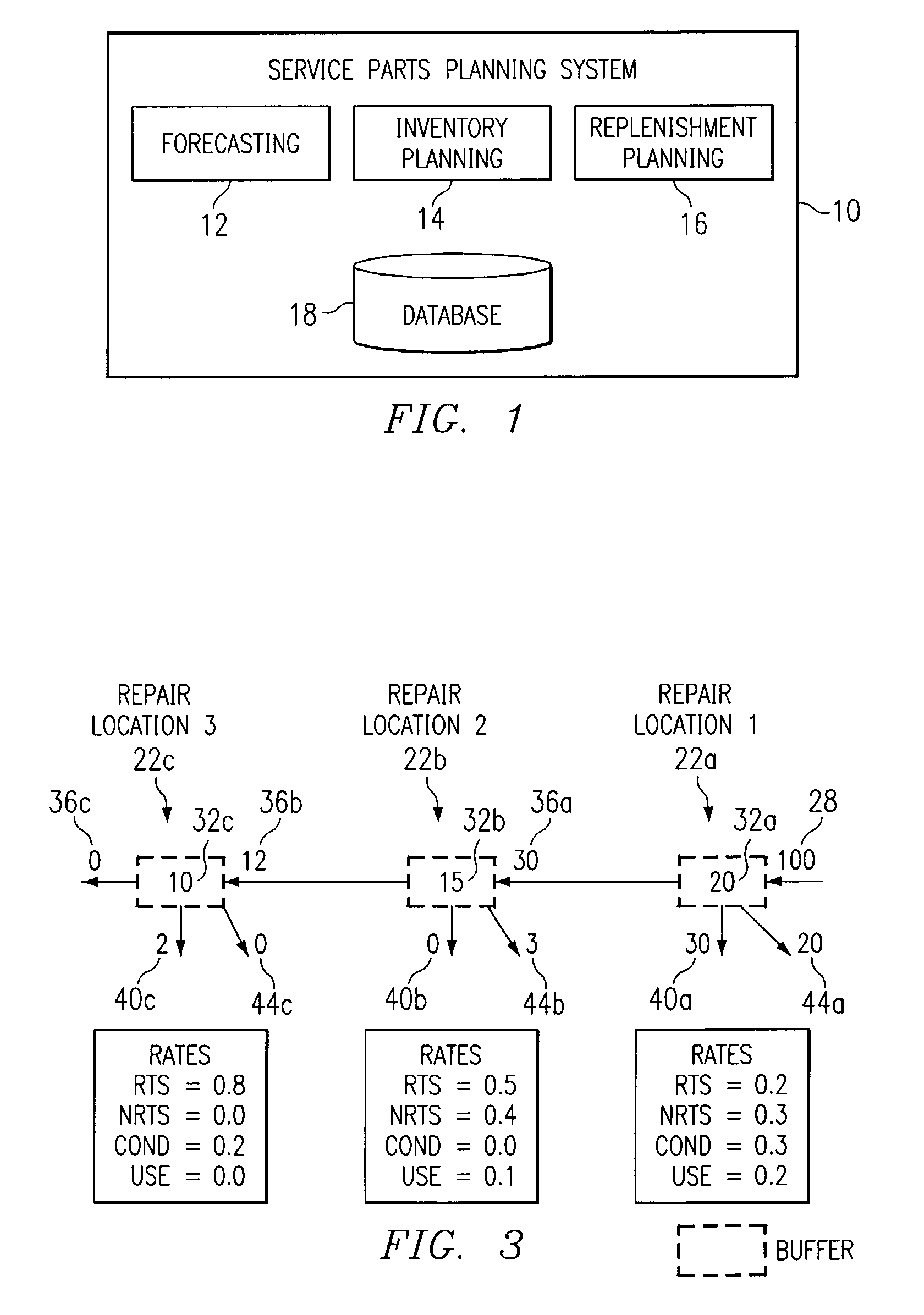
[0017]FIG. 1 illustrates an example service parts planning system 10. In general, system 10 generates plans relating to supply of service parts to replace broken or otherwise unusable parts. For example, unusable parts may include parts that were unusable at the time the parts were manufactured, parts that became unusable during service, or any other unusable parts.

[0018]In one embodiment, system 10 includes a forecasting engine 12 that generates demand forecasts for service parts based on future estimates regarding the number of parts that will break or otherwise become unusable and will need to be replaced. A separate demand forecast may be generated for each of a number of service parts for each of a number of forecasting periods. For example, forecasting engine 12 may generate a new demand forecast for a particular part each month for a specified time period in the future. The time period for a demand forecast is preferably longer than the time to complete the longest expected r...


PUM


Abstract

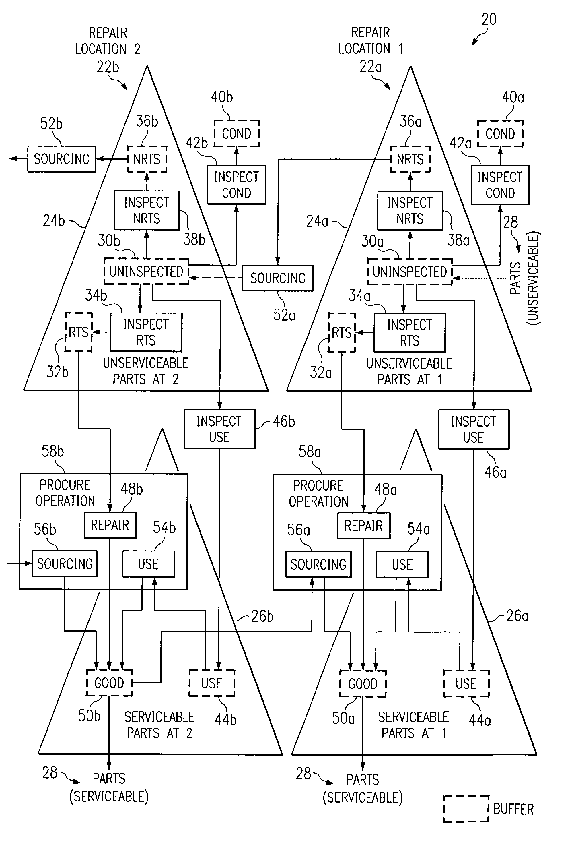
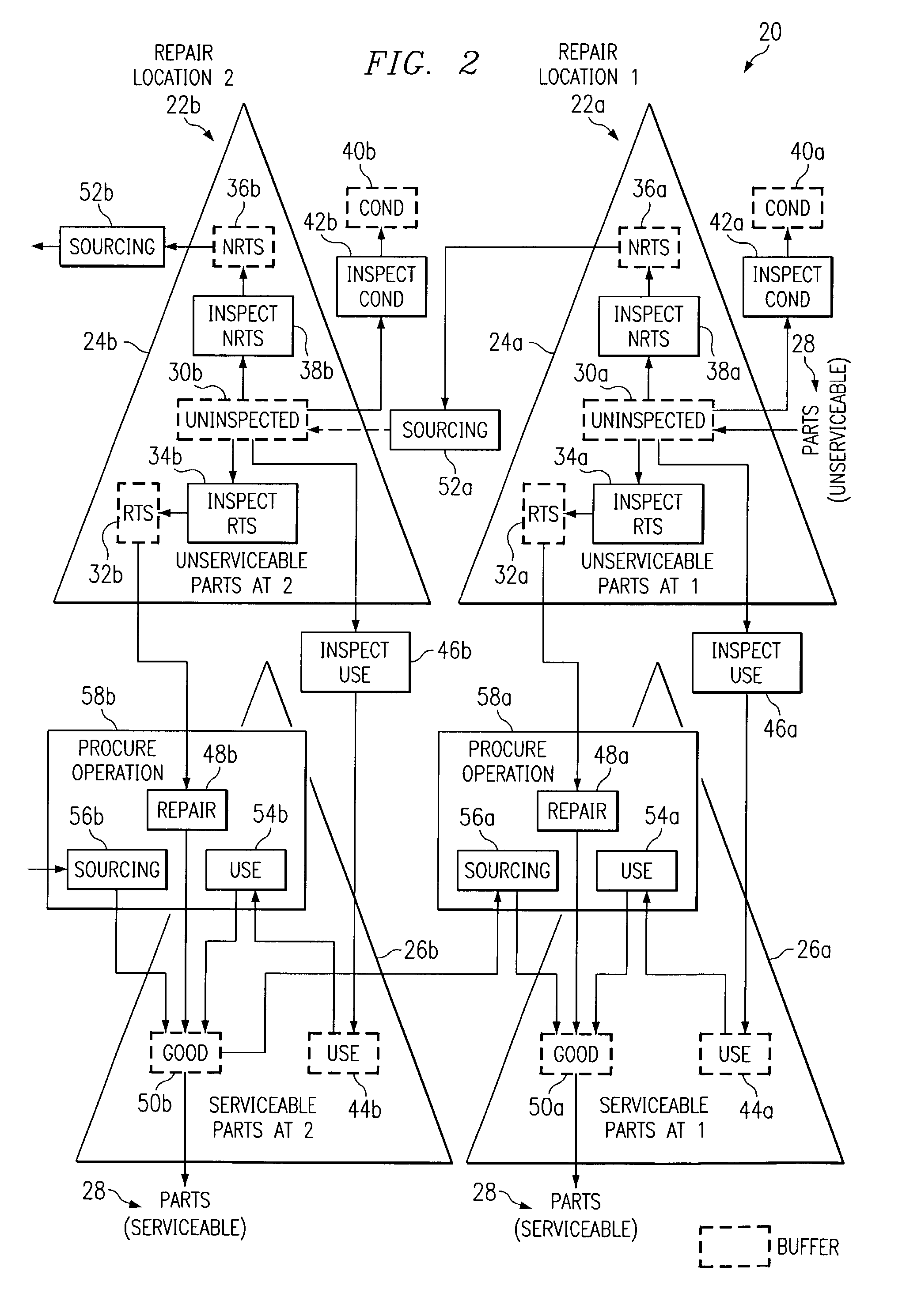
In one embodiment, a method for repair planning for a location in a repair network includes modeling: (1) an uninspected buffer for parts received but not yet inspected at the location; (2) a first buffer for parts inspected at the location and repairable at the location; (3) a second buffer for parts inspected at the location and not repairable at the location; (4) a third buffer for parts inspected at the location and not repairable at any location in the repair network; and (5) a fourth buffer for parts inspected at the location and serviceable without repair. The parts in the uninspected buffer are assigned to the first, second, third, and fourth buffers at corresponding rates according to an inspection operation. One or more operation plans are generated to push parts out of the uninspected buffer to the first, second, third, and fourth buffers according to the corresponding rates, a part pushed out being available within the first, second, third, or fourth buffer only after a predetermined disposition time has elapsed. An operation plan is generated to push parts out of the second buffer to one or more upstream locations, a part pushed out being available at an upstream location only after a predetermined move lead time has elapsed. For each part pushed out of the uninspected buffer to the first or second buffer, the earliest time at which repair can begin for the part is estimated, this earliest repair time determining the earliest time at which, after the part has been repaired to make it serviceable, the part can be available to satisfy a demand at the location.

Description

RELATED APPLICATIONS[0001]This application is related to U.S. application Ser. No. 10 / 223,845 filed Aug. 19, 2002, entitled “On-Demand Repair Planning,” and U.S. Application No. 10 / 224,240 filed Aug. 19, 2002, entitled “Pull Planning for Serviceable Parts to Facilitate On-Demand Repair Planning,” both by Amol B. Adgaonkar, Deepak Rammohan, Pradip Som, and Thomas Burkhardt. U.S. application Ser. No. 10 / 223,845 and U.S. application Ser. No. 10 / 224,240 are commonly assigned to the assignee of the present invention. The disclosures of the related patent applications are hereby incorporated by reference for all purposes as if fully set forth herein.TECHNICAL FIELD OF THE INVENTION[0002]This invention relates generally to service parts planning and more particularly to push planning for unserviceable parts to facilitate repair planning in a repair network.BACKGROUND OF THE INVENTION[0003]A critical aspect of many supply chains is a network of repair locations that cooperate to receive, di...

Claims


Application Information

Patent Timeline
IPC IPC(8): G05B19/418G06F9/46G06Q10/06
CPCG06Q10/06315G06Q10/06
Inventor ADGAONKAR, AMOL B.RAMMOHAN, DEEPAKSOM, PRADIPBURKHARDT, THOMAS
Owner BLUE YONDER GRP INC
Learn More