Eureka AIR delivers breakthrough ideas for toughest innovation challenges, trusted by R&D personnel around the world.

Process for the manufacture by lost wax moulding of parts that include at least one cavity

a technology of lost wax and parts, applied in the field of turbines, can solve the problems of high rejection rate, process does not allow one to obtain parts, and the cones are no longer sufficient to guarantee the quality of the part, and achieve the effect of controlling the wall thickness and low thickness

Active Publication Date: 2007-10-02
SN DETUDE & DE CONSTR DE MOTEURS DAVIATION S N E C M A
View PDF9 Cites 16 Cited by
  • Summary
  • Abstract
  • Description
  • Claims
  • Application Information

AI Technical Summary

Benefits of technology

[0016]The purpose of the invention is to remedy these drawbacks, and to control the wall thicknessess,

Problems solved by technology

The cones are no longer sufficient to guarantee the quality of the part, since they are removed with the wax at the moment of dewaxing the mould.
When this operation is manual, it cannot be fully controlled, and this may give rise to significantly uneven wall thicknesses and lead to a high rejection rate.
It can also be seen that the process does not allow one to obtain a part whose quality is optimal.
The critical area of the blade is neither

Method used


Image

  • Process for the manufacture by lost wax moulding of parts that include at least one cavity
  • Process for the manufacture by lost wax moulding of parts that include at least one cavity
  • Process for the manufacture by lost wax moulding of parts that include at least one cavity

Examples


Embodiment Construction

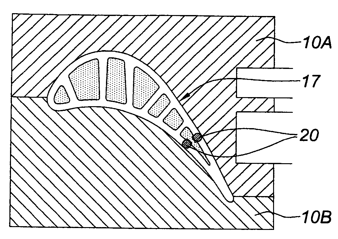
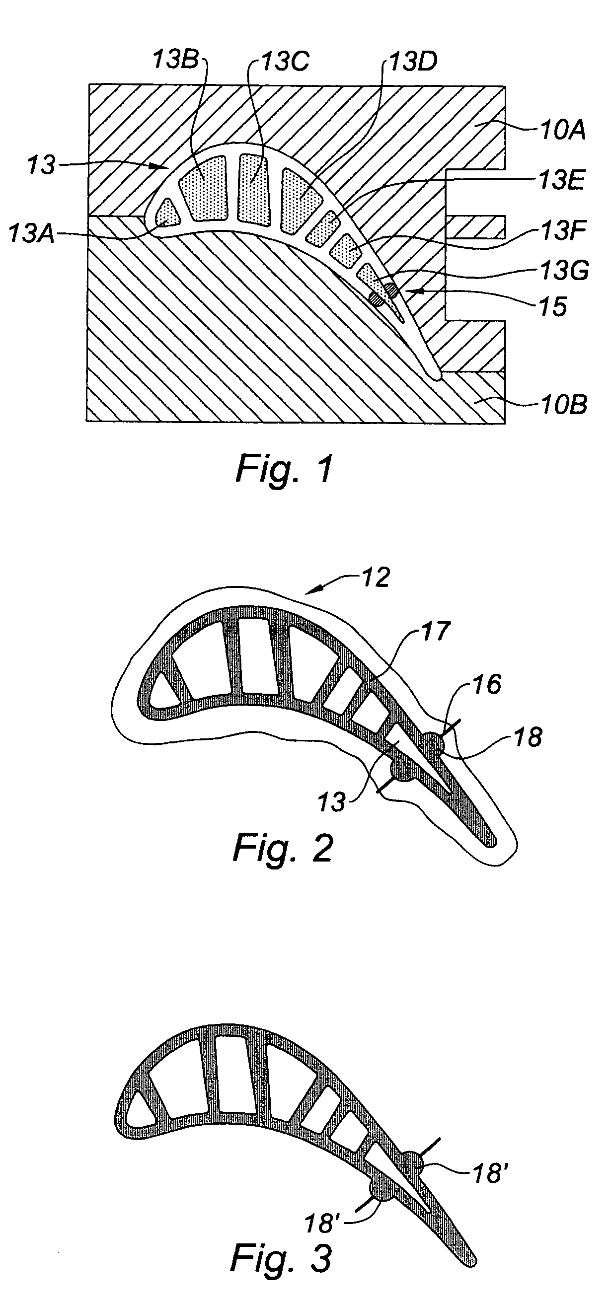
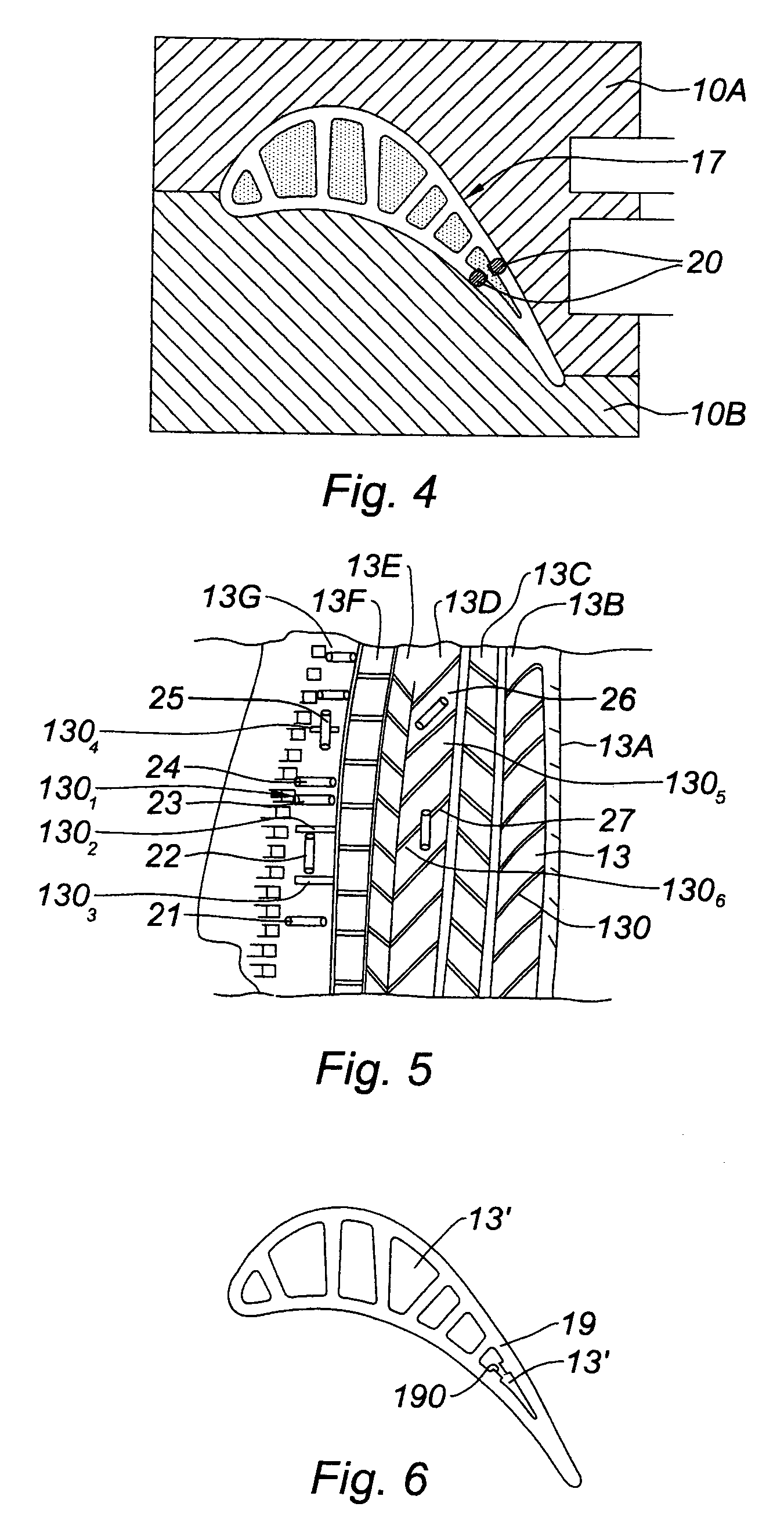
[0038]Referring directly to FIG. 4, we see the model of the part, which is a blade of the same profile as that of the previous state of the art as presented earlier. We find the core 13 inserted into the two halves 10A and 10B of the wax mould 10. The core 13 is enclosed in a covering of wax 17 which has been injected into the mould and which occupies all of the empty spaces between the different elements of the core on one hand, and between the core and the internal wall of the mould on the other. According to the invention, platinum spacing elements 20 have been positioned at the formation of the model in the mould.

[0039]The platinum can be replaced with another material, depending on the nature of the metal used for the casting process. These elements are embedded into the thickness of the wax covering 17. They are flush with the outer surface of the wax covering after extraction of the model. These elements 20 are in particular positioned approximately at the same place as in th...


PUM

PropertyMeasurementUnit
Angleaaaaaaaaaa
Flow rateaaaaaaaaaa
Timeaaaaaaaaaa

Abstract

A process for the manufacture of a part includes the steps of forming a core in a ceramic material, inserting the core into in a wax mold, placing an element on the core thereby forming a spacer between the core and an internal wall of the wax mold, forming a wax model of the part with the core by injecting wax into the mold, forming a shell mold in ceramic material from the wax model, removing the wax, and pouring casting metal into the shell mold, wherein the element is of elongated form and placed on the core in a laying position.

Description

BACKGROUND OF THE INVENTION[0001]1. Field of the Invention[0002]This present invention concerns the area of turbines, in particular that of the turbines of gas-turbine engines, and is aiming at a process for the manufacture by lost wax moulding of parts, in particular of blades, including cavities intended for the circulation of cooling fluids.[0003]2. Description of the Related Art[0004]The blades of turbines that are subjected to high thermal stresses include resources for cooling by the circulation of a cooling fluid, generally of air in the case of a gas-turbine engine, within cavities created within the blade.[0005]Furthermore, the blades of turbines are now generally manufactured by the lost wax moulding process. This technique consists of creating a model in wax or another equivalent temporary material, of the part that one wishes to mould. The model is then placed in a ceramic shell mould. The latter is manufactured by successive dipping of the model in slurry mixtures conta...

Claims


Application Information

Patent Timeline
IPC IPC(8): B22C9/04B29D99/00B22C21/14
CPCB22C21/14B22C9/04B29C67/241B29C33/304
Inventor GUERCHE, DIDIERTABARDIN, JACKY PIERRE
Owner SN DETUDE & DE CONSTR DE MOTEURS DAVIATION S N E C M A
Why Eureka
Eureka Blog
Learn More