
Control device for electric compressor

a control device and electric compressor technology, applied in the direction of positive displacement liquid engines, piston pumps, liquid fuel engines, etc., can solve the problems of affecting the electric compressor integrated with the control device cannot have a sufficient size for a control substrate, and the noise is likely to degrade the value of vehicles as products

Active Publication Date: 2007-09-25
MITSUBISHI HEAVY IND LTD
View PDF9 Cites 14 Cited by
  • Summary
  • Abstract
  • Description
  • Claims
  • Application Information

AI Technical Summary

Benefits of technology

The present invention relates to a control device for an electric compressor in a vehicle-mounted air conditioner. The technical problem addressed by the invention is to provide a control device that can reduce the size of the control device and the mounting space needed for it, while also protecting the internal circuit of the control device from heat and electromagnetic waves generated by the engine or large motor of the vehicle. Additionally, the invention aims to improve the stability and control of the electric compressor by eliminating noise and ensuring smooth operation of the motor.

Problems solved by technology

In the sensorless control for the permanent-magnet synchronous motor, synchronized operation cannot be performed immediately because a rotor position is unknown at the time of starting of the motor.
However, such housing of the electric compressor integrated with the control device does not have a sufficient size for a size of a control substrate.
As the size of the control device decreases, circuit malfunction due to noise mainly caused by the switching device in the housing occurs, and an influence of heat generated from the device on other devices causes problems.
Moreover, in a control performed by such control device, the compressor connected to the rotor does not operate stably and causes a noise.
Therefore, the noise is likely to degrade values of the vehicles as products.
If the electric compressor is controlled without grasping a position of the rotor, the likelihood of failure in starting the motor increases.

Method used


Image

  • Control device for electric compressor
  • Control device for electric compressor
  • Control device for electric compressor

Examples


Embodiment Construction

[0036]Exemplary embodiments according to the present invention are explained in detail below with reference to the accompanying drawings.

[0037]A control device for an electric compressor according to the present invention is suitable for manufacturing and use of a control device of a permanent-magnet synchronous motor built in or connected to an electric compressor used in a vehicle-mounted air conditioner.

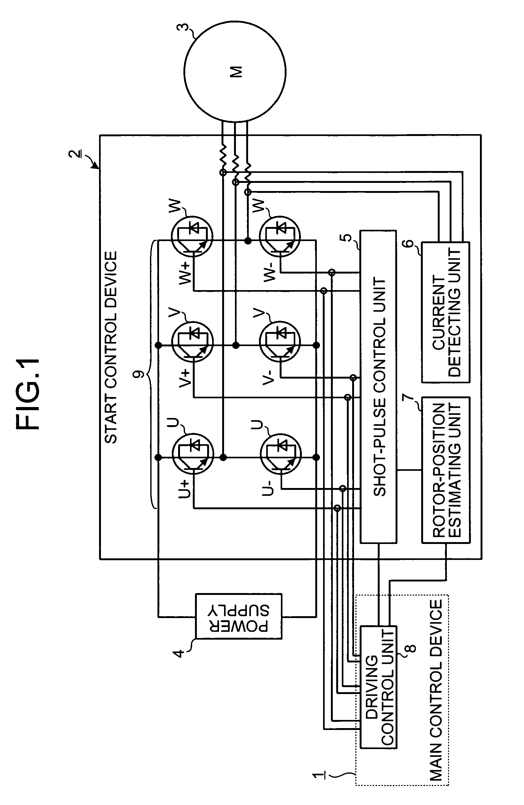
[0038]FIG. 1 is a schematic diagram of a configuration according to an embodiment of the present invention. Usually, in an electric compressor used in a vehicle-mounted air conditioner, a permanent-magnet synchronous motor (hereinafter, “motor”) 3 provided in or connected to the vehicle-mounted air conditioner is subjected to inverter control using a stationary direct current (DC) battery as a power supply 4. In the embodiment, the motor 3 is subjected to the inverter control in a similar manner.

[0039]Control for the motor 3 at a steady operation is performed in a driving control ...


PUM


Abstract

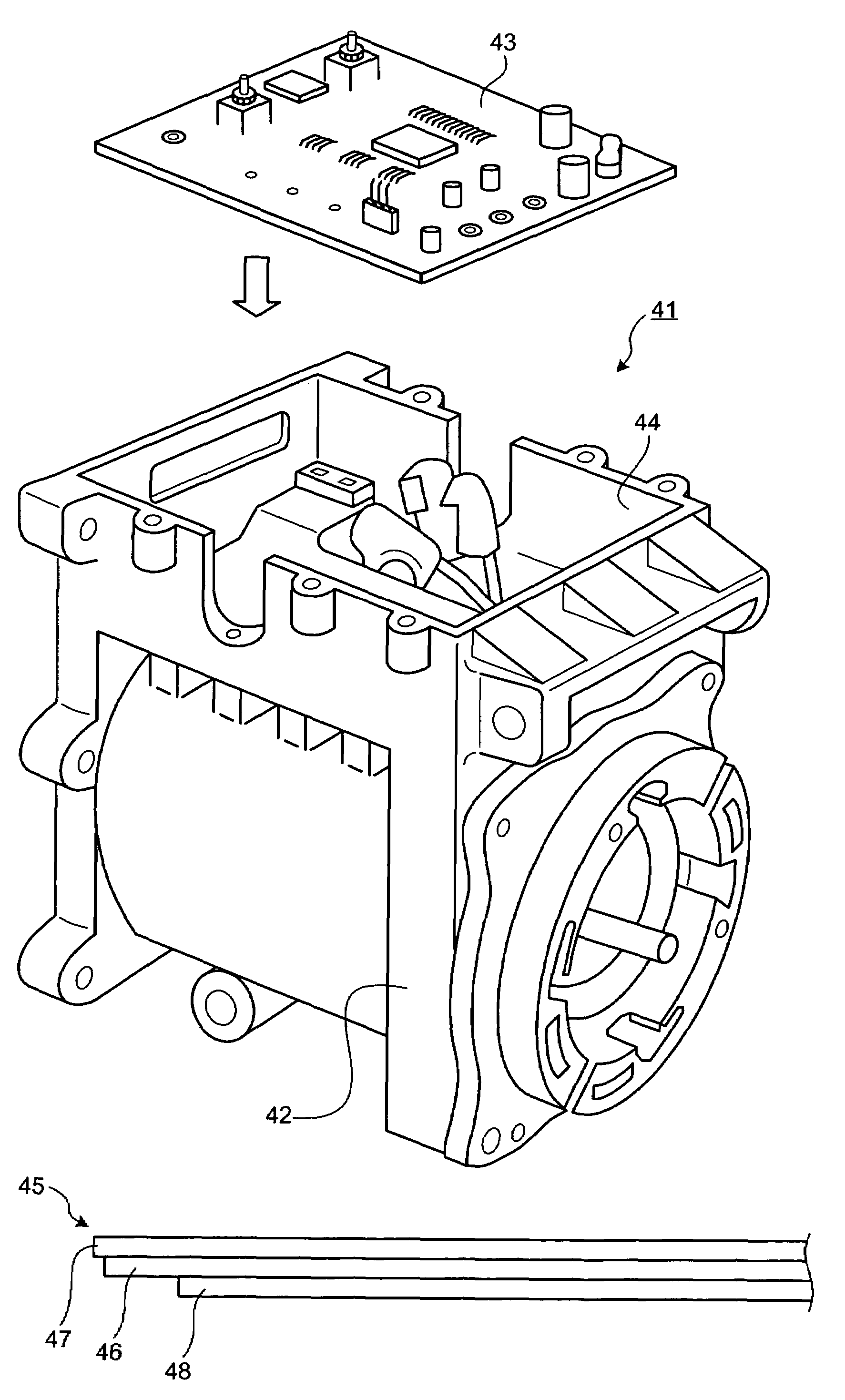
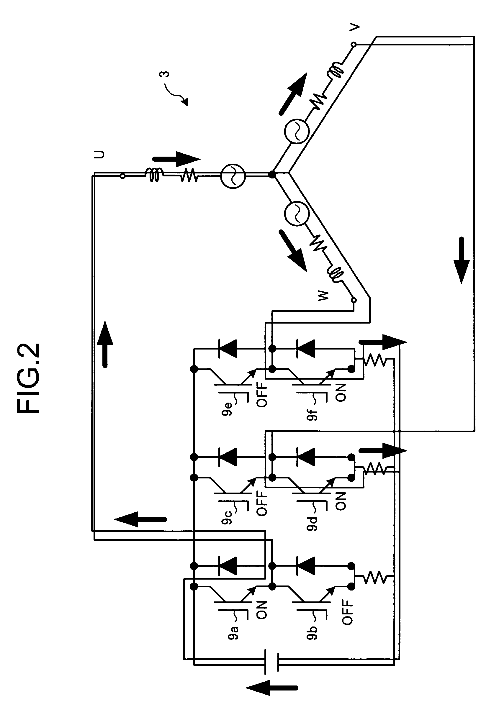
A control device includes a shot-pulse control unit that provides, at a time of starting a synchronous motor, a predetermined current to each phase of a stator of the motor for a short time; a detecting unit that detects a current flowing through each phase when the predetermined current is provided; an estimating unit that estimates a position of the rotor by comparing detected values; a voltage control unit that controls application of a voltage to the synchronous motor based on a high-pressure side pressure of the compressor when the compressor is failed to be started due to any cause; and a magnetism-resistant section having a conductive layer sandwiched by insulating layers. The magnetism-resistant section covers a portion of a substrate of the control device, and a portion at which the conductive layer is exposed is in contact with the housing or a part conducting heat to the housing.

Description

CROSS-REFERENCE TO RELATED APPLICATIONS[0001]This application is based upon and claims the benefit of priority from Japanese Patent Application No. 2005-232066, filed Aug. 10, 2005; Japanese Patent Application No. 2005-241157, filed Aug. 23, 2005, and Japanese Patent Application No. 2005-241156, filed Aug. 23, 2005, the entire contents of which are incorporated herein by reference.BACKGROUND OF THE INVENTION[0002]1. Field of the Invention[0003]The present invention relates to a control device for an electric compressor in a vehicle-mounted air conditioner.[0004]2. Description of the Related Art[0005]In an electric vehicle-mounted air conditioner mounted on a hybrid vehicle, a fuel cell electric vehicle (FCEV), and a hydrogen vehicle, so-called sensorless control is generally used as control for an electric compressor. In the sensorless control for the permanent-magnet synchronous motor, synchronized operation cannot be performed immediately because a rotor position is unknown at the...

Claims


Application Information

Patent Timeline
Patent Type & Authority Patents(United States)
IPC IPC(8): F04B23/00
CPCH02P6/185F04C2270/60F04C2270/80F04C14/06H02P6/20H02K11/01
Inventor HATTORI, MAKOTOASAI, MASAHIKOTAKASHIGE, TAKAYUKINAKANO, KOJINAKAGAMI, TAKASHI
Owner MITSUBISHI HEAVY IND LTD
Learn More