
Network interface for distributed intelligence database system

a database system and network interface technology, applied in the field of database systems, can solve the problems of unsolved problems, unnecessari delay and complexity of the use of reliable delivery mechanisms, and the introduction of a layer of complexity and delay in the efficient processing of database application primitives

Inactive Publication Date: 2007-09-18
IBM CORP
View PDF28 Cites 104 Cited by
  • Summary
  • Abstract
  • Description
  • Claims
  • Application Information

AI Technical Summary

Benefits of technology

The patent describes an application that can keep track of connections it has made in order to deliver messages reliably. This helps ensure that the system works well even when there are many people trying to use it at once.

Problems solved by technology

The technical problem addressed in this patent is how to implement intelligent decision-making capabilities within communication processes related to mass storage sub-systems used in database applications.

Method used


Image

  • Network interface for distributed intelligence database system
  • Network interface for distributed intelligence database system
  • Network interface for distributed intelligence database system

Examples


Embodiment Construction

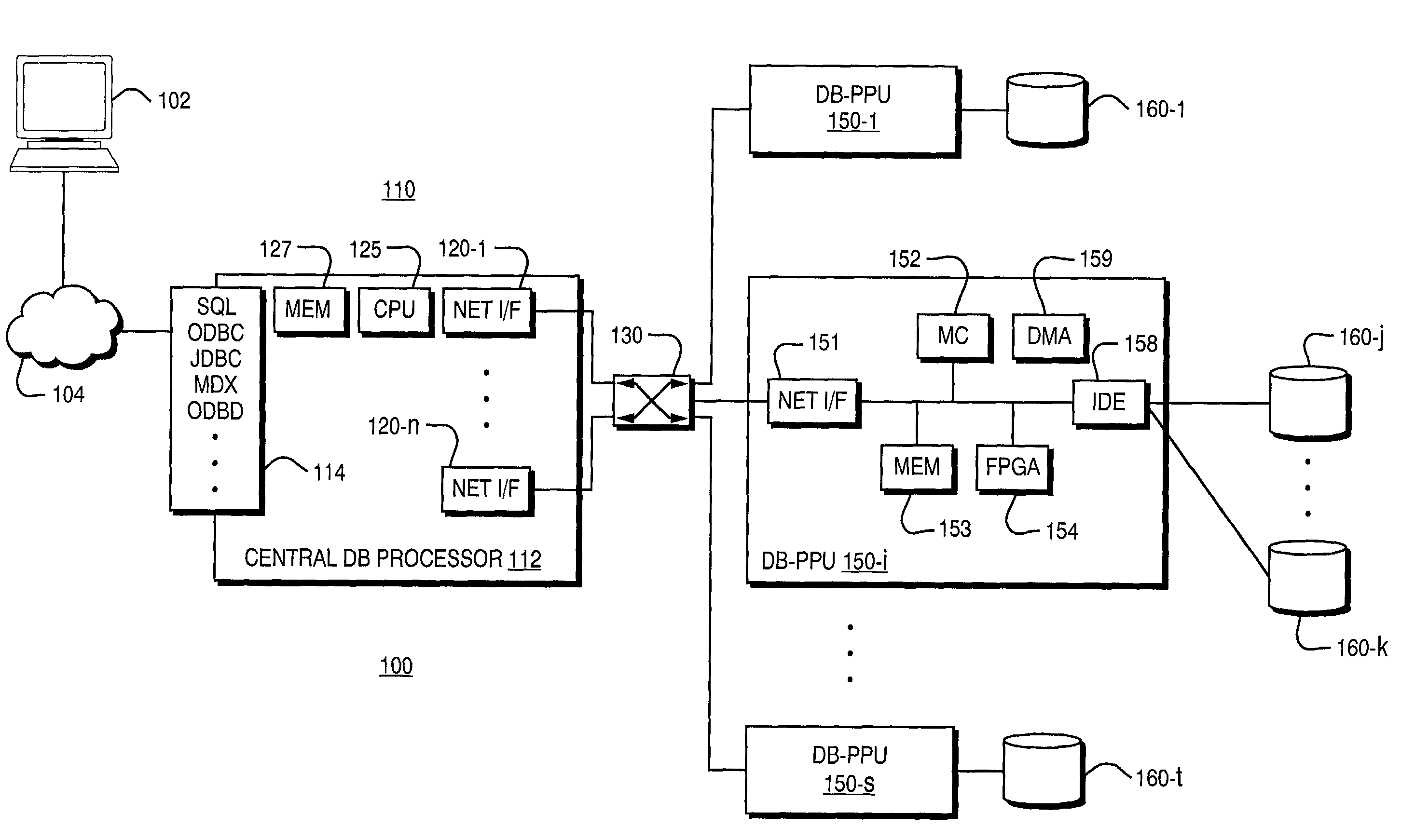
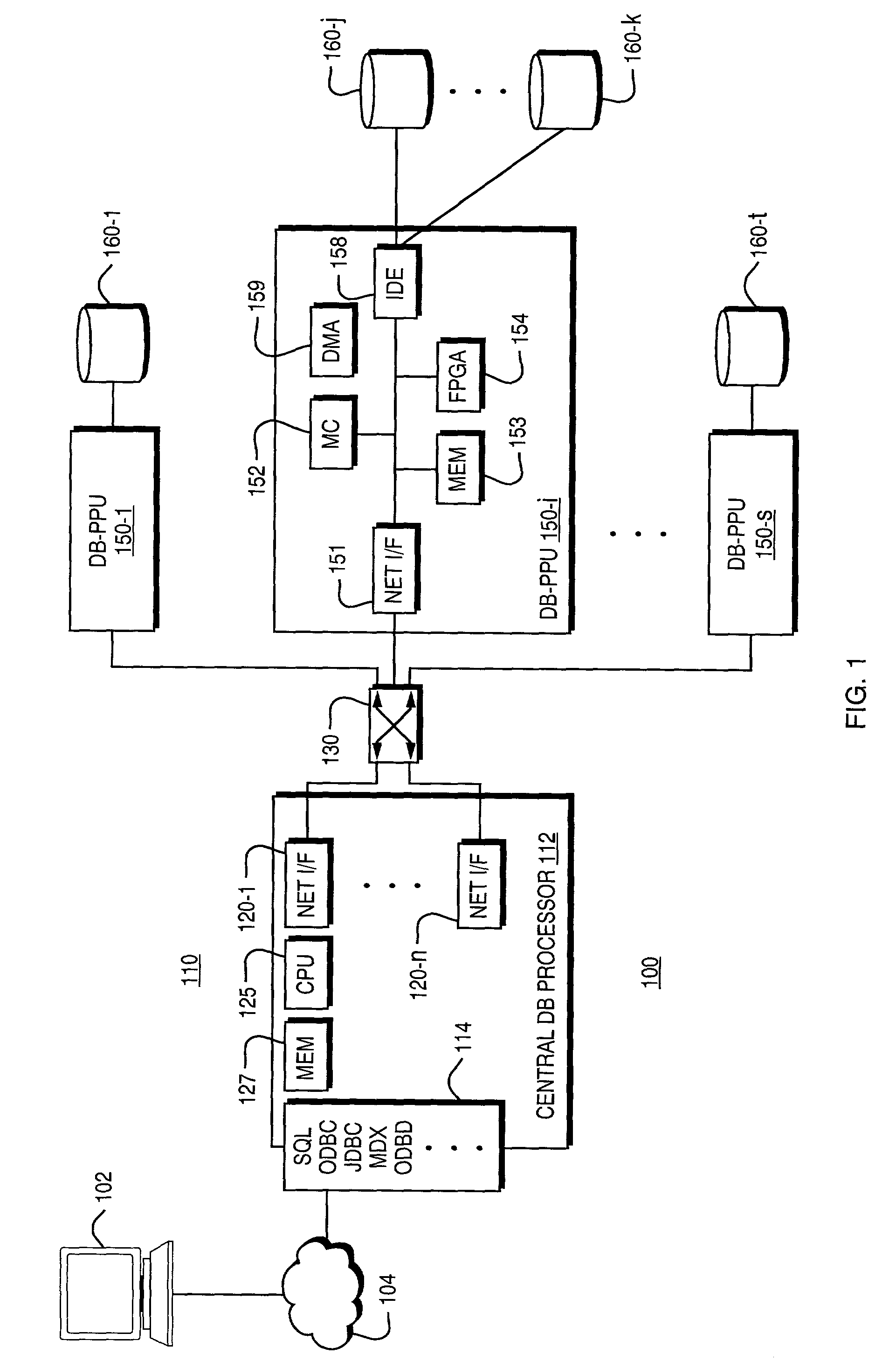
[0026]The present invention provides for efficient, reliable streaming transmission of database information across a network between a sender and one or more receivers. FIG. 1 is illustrative of a system architecture 100 in which the invention may be used. The system 100 consists of a user interface or client device 102, a generalized computer network connection 104, a central database processor 110, a data network 130, one or more database operation processing units (DB-PPUs) 150-1, 150-i . . . , 150-s, and a plurality of mass storage devices such as disk drives 160-1 . . . 160-j, . . . 160-k, . . . 160-t. A database is stored and accessible on the disk drives 160, which may be mirrored, striped, or formatted in a number of different ways. It should be understood that more than one physical disk drive 160-j, . . . , 160-k may be associated with a particular database operation processing unit 150-i. Examples of databases that can be stored and operated on by this system include but ...


PUM


Abstract

A database appliance having multiple internetworked data storage units and central database processing units. The central database processors and storage units communicate as network nodes. Execution of a distributed database application is coordinated by a communication process such that data blocks are passed by using data block reference information. Operations executing within the same context as the communication process may include join, sort, aggregate, restrict, reject, expression evaluation, statistical analysis or other database operations.

Description


Claims


Application Information

Patent Timeline
Owner IBM CORP
Learn More