
Antenna device with improved isolation characteristic

a technology of isolation characteristic and antenna device, which is applied in the structure of radiating elements, substantially flat resonant elements, and resonant antennas, etc., can solve the problems of deteriorating isolation characteristic, troublesome antenna performance, and inability to promote so as to achieve the effect of ensuring isolation characteristic, promoting the size reduction of the entire device, and reducing the size of the entire devi

Active Publication Date: 2007-09-18
ALPS ALPINE CO LTD
View PDF6 Cites 15 Cited by
  • Summary
  • Abstract
  • Description
  • Claims
  • Application Information

AI Technical Summary

Benefits of technology

This configuration ensures a favorable isolation characteristic even with a narrow gap, allowing for significant size reduction without degrading performance, and can be manufactured at lower costs using sheet metal, while maintaining resonance and efficiency.

Problems solved by technology

Accordingly, the radiation electric fields of the individual radiating slots are intensively coupled to each other, which results in deterioration of the isolation characteristic.
That is, when it is going to promote the entire device to be reduced in size, the isolation characteristic deteriorates, which tends to cause a trouble in antenna performance.
To the contrary, when it is going to insure a desired isolation characteristic, there is a problem in that it is impossible to promote the entire device to be reduced in size.
Moreover, in such an antenna device, if the isolation characteristic is not favorable, in a transmission mode, radiation efficiency gets worse, and also, in a reception mode, a desired beam pattern cannot be formed.

Method used


Image

  • Antenna device with improved isolation characteristic
  • Antenna device with improved isolation characteristic
  • Antenna device with improved isolation characteristic

Examples


first embodiment

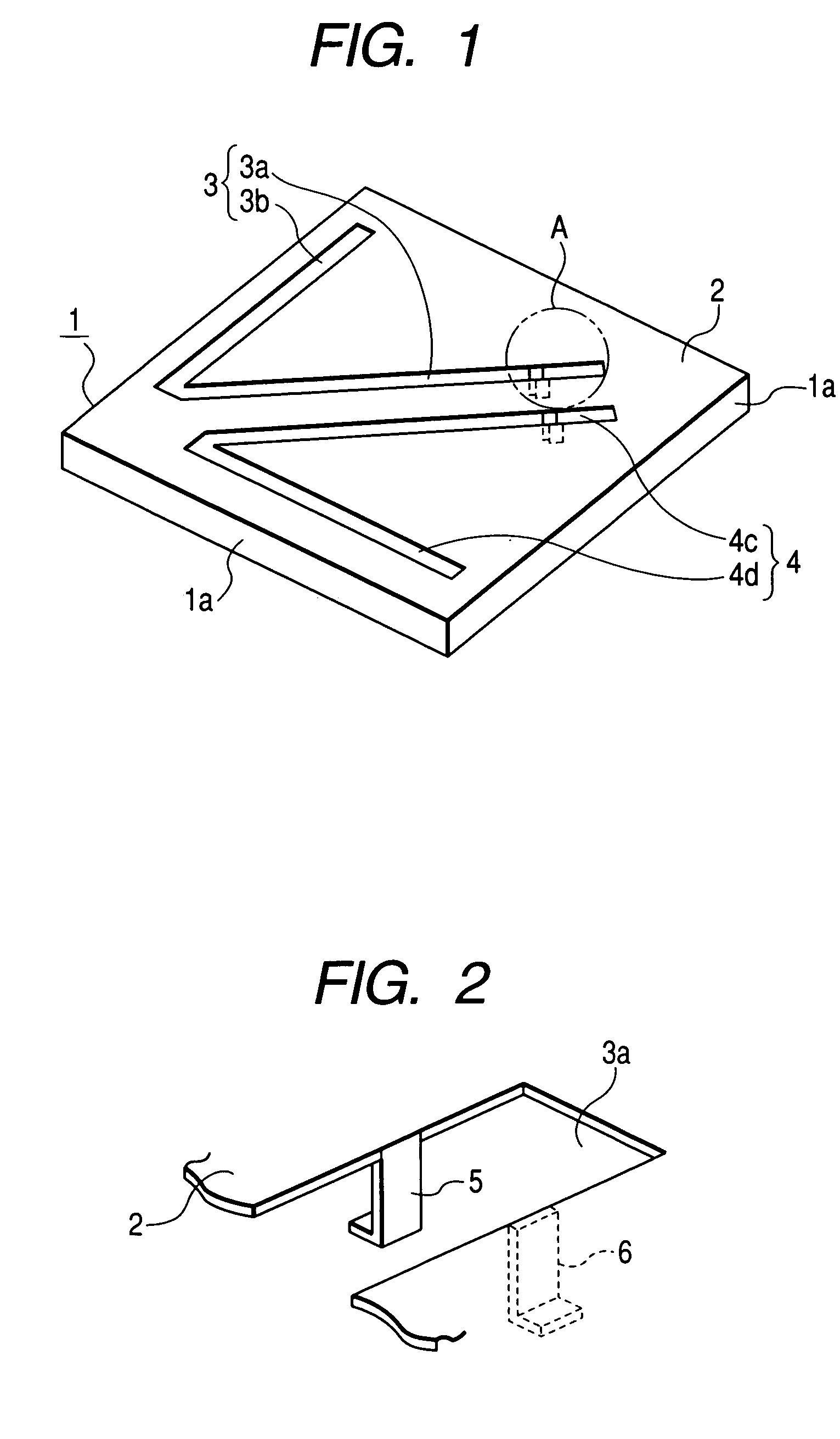
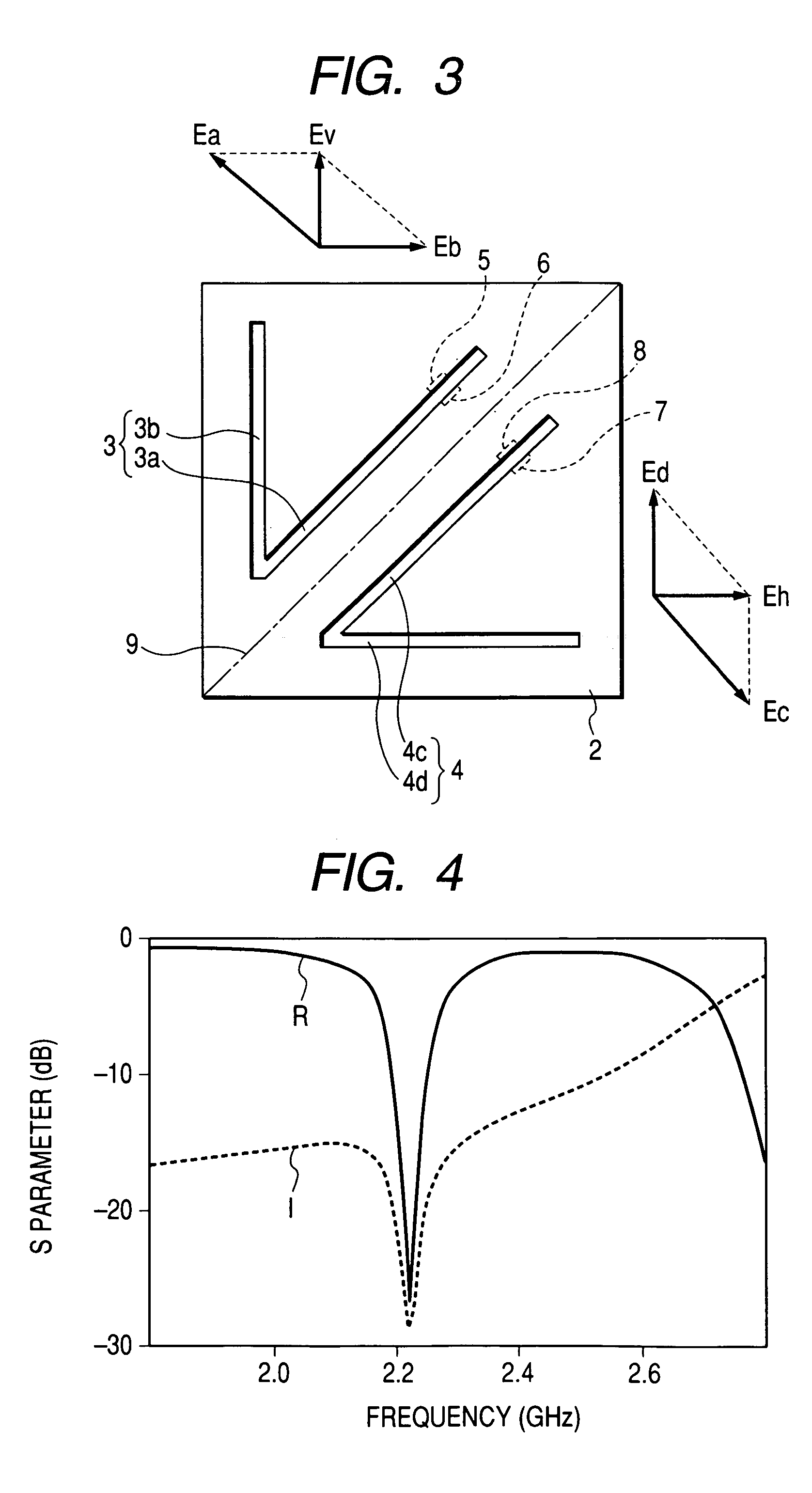
[0020]Embodiments of the invention will be described with reference to the drawings. FIG. 1 is a perspective view of an antenna device according to the invention. FIG. 2 is an expanded view of an A portion in FIG. 1. FIG. 3 is a plan view of the antenna device. FIG. 4 is a characteristic diagram showing an S parameter of the antenna device.

[0021]The antenna device showing in FIGS. 1 to 3 is schematically configured to have a boxlike metal case 1, a top plate of which is formed of a flat metal plate 2 having a square shape, a pair of radiating slots 3 and 4 that open in the metal plate 2, a power feeding line 5 and a ground line 6 that extend downward from power feeding positions of one radiating slot 3, and a power feeding line 7 and a ground line 8 that extend downward from power feeding positions of the other radiating slot 4.

[0022]The metal case 1 is obtained by pressing a sheet metal. The metal case 1 is molded in a box shape by bending four side plates downward from individual ...

second embodiment

[0030]FIG. 5 is a plan view of an antenna device according to the invention. In FIG. 5, the same parts as those in FIG. 3 are represented by the same reference numerals, and the descriptions thereof will be omitted.

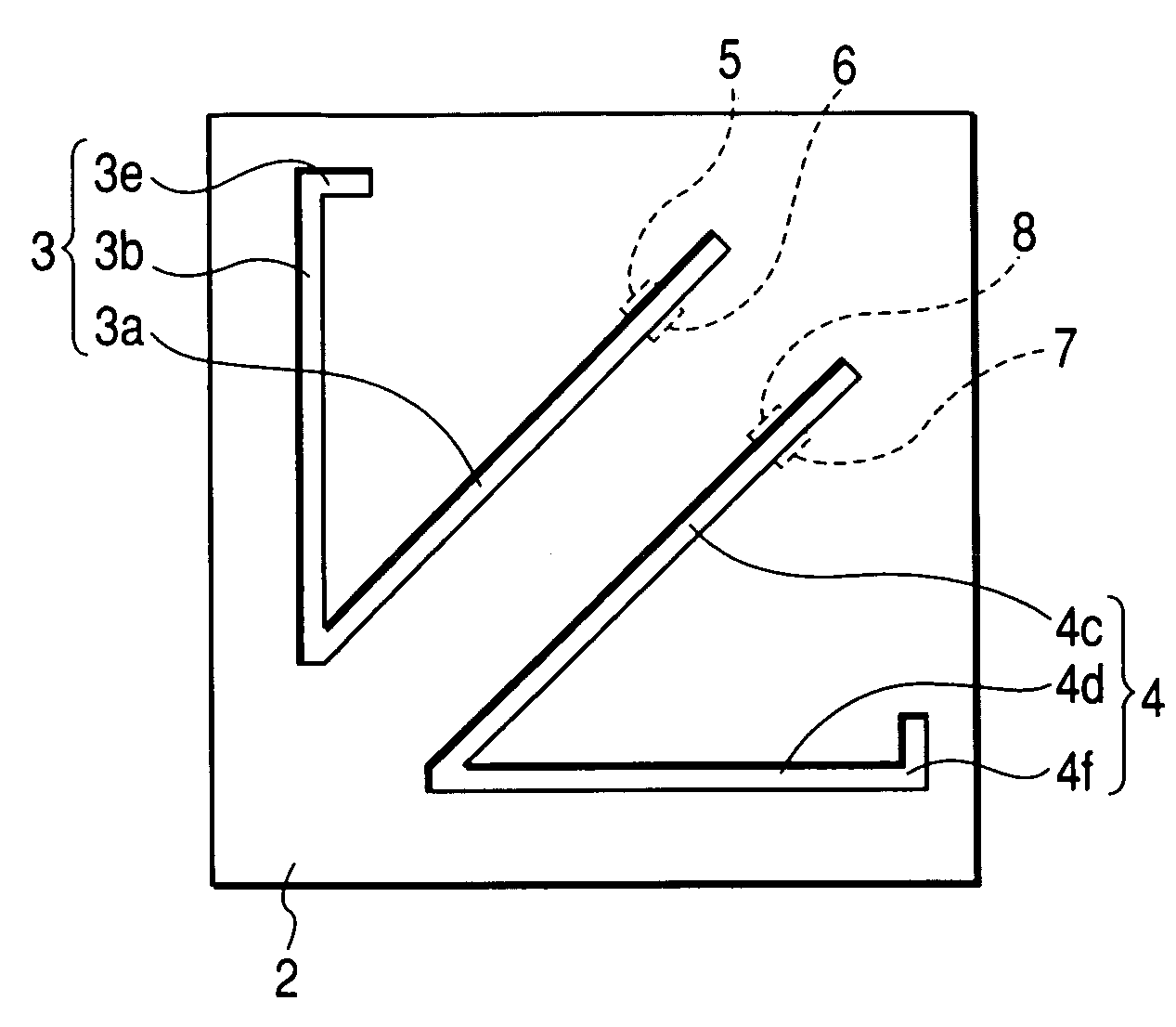
[0031]An antenna device shown in FIG. 5 is different from the first embodiment of the invention in that the radiating slots 3 and 4 have third slot portions 3e and 4f at the front ends of the second slot portions 3b and 4d, respectively. That is, in the radiating slot 3, in addition to the first and second slot portions 3a and 3b, the short third slot portion 3e is provided to be connected to an end of the second slot portion 3b opposite to the side which is connected to the first slot portion 3a. The third slot portion 3e extends along an outer edge (upper side in FIG. 5) of the flat metal plate 2. Similarly, in the radiating slot 4, in addition to the first and second slot portions 4c and 4d, the short third slot portion 4f is provided to be connected to an end of the s...


PUM


Abstract

A pair of radiating slots open in a flat metal plate having a square shape to be line-symmetrically arranged with respect to a symmetry axis, and power feeding lines and ground lines are provided at power feeding positions of the respective radiating slots. The respective radiating slots have first slot portions and second slot portions that contact at 45 degrees and linearly extend, respectively. Both the radiating slots are arranged in a back-to-back manner that edges of the first slot portions face each other, and the second slot portions extend in a direction to be separated from each other along two sides of the flat metal plate. Further, a polarization direction of an electric wave to be generated by one radiating slot and a polarization direction of an electric wave to be generated by the other radiating slot are set to be perpendicular to each other.

Description

BACKGROUND OF THE INVENTION[0001]1. Field of the Invention[0002]The present invention relates to a small antenna device in which a pair of radiating slots are provided to constitute a diversity antenna.[0003]2. Description of the Related Art[0004]As the related art of such an antenna device, as shown in FIG. 6, a configuration is known in which a pair of radiating slots 32 and 33 open in a metal case 31 of a wireless LAN card 30 and are electromagnetically coupled to microstrip lines 34 and 35 to be fed, respectively (for example, see Japanese Unexamined Patent Application Publication No. 2003-234615 (pages 3-4 and FIG. 1)). Each of the radiating slots 32 and 33 opens in an L shape to extend along the external shape of the metal case 31. Since one end of the radiating slot 32 faces one end of the radiating slot 33, the pair of radiating slots 32 and 33 are line-symmetrically arranged. The microstrip lines 34 and 35 are formed in a circuit board 36 housed in the metal case 31 so as t...

Claims


Application Information

Patent Timeline
Patent Type & Authority Patents(United States)
IPC IPC(8): H01Q13/10H01Q1/36
CPCH01Q9/0407
Inventor YUANZHU, DOU
Owner ALPS ALPINE CO LTD
Learn More