
Media for laser imaging

a laser imaging and media technology, applied in thermography, instruments, photosensitive materials, etc., can solve the problems of damage or chemical decomposition of the media being printed, the cost of microstructure image formation, and the need for complicated and dangerous lasers

Active Publication Date: 2007-09-18
HEWLETT PACKARD DEV CO LP
View PDF14 Cites 16 Cited by
  • Summary
  • Abstract
  • Description
  • Claims
  • Application Information

AI Technical Summary

Benefits of technology

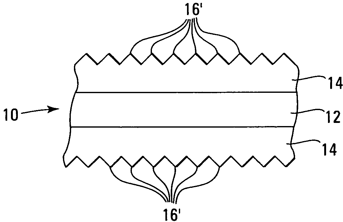
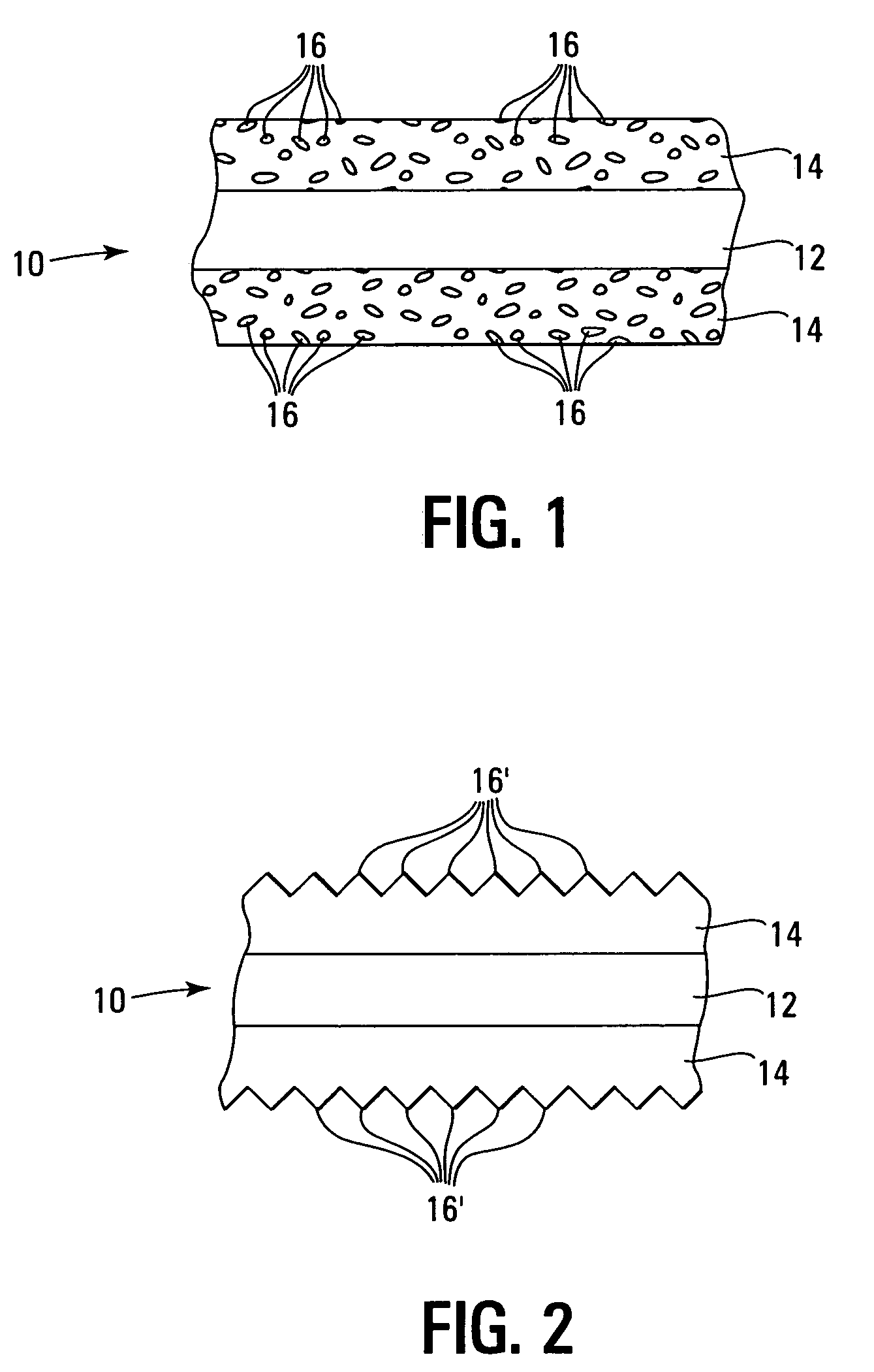
The present invention is a method of printing that involves applying microstructures with a chosen optical characteristic to a printing medium. The microstructures absorb radiation within a specific range of wavelengths and convert it to heat energy. This heat energy is then absorbed by a radiation antenna that is selectively sensitive to the applied radiation. The printing medium can be a coated or uncoated substrate with microstructures applied to it. The printing mechanism includes one or more source radiation sources that output light within the range of wavelengths that are sensitive to the radiation antenna in the medium. The technical effect of this invention is the ability to create printed materials that have specific optical characteristics, such as color, using microstructures that absorb radiation and convert it to heat energy.

Problems solved by technology

In short, the formation of images on media using microstructures is relatively expensive, requires complicated and dangerous lasers, and / or may damage or chemically decompose the media being printed.

Method used


Image

  • Media for laser imaging
  • Media for laser imaging
  • Media for laser imaging

Examples


Embodiment Construction

[0019]In the following detailed description of the invention, reference is made to the accompanying drawings that form a part hereof and in which is shown, by way of illustration, specific embodiments in which the invention may be practiced. In the drawings, like numerals describe substantially similar components throughout the several views. These embodiments are described in sufficient detail to enable those skilled in the art to practice the invention. Other embodiments may be utilized and structural, logical, and electrical changes may be made without departing from the scope of the present invention. The following detailed description is, therefore, not to be taken in a limiting sense, and the scope of the present invention is defined only by the appended claims and equivalents thereof.

[0020]The present invention generally includes a medium for printing and a method of printing that involves the use of certain types of microstructures in conjunction with radiation sources and r...


PUM

PropertyMeasurementUnit
wavelengthsaaaaaaaaaa
wavelengthaaaaaaaaaa

Abstract

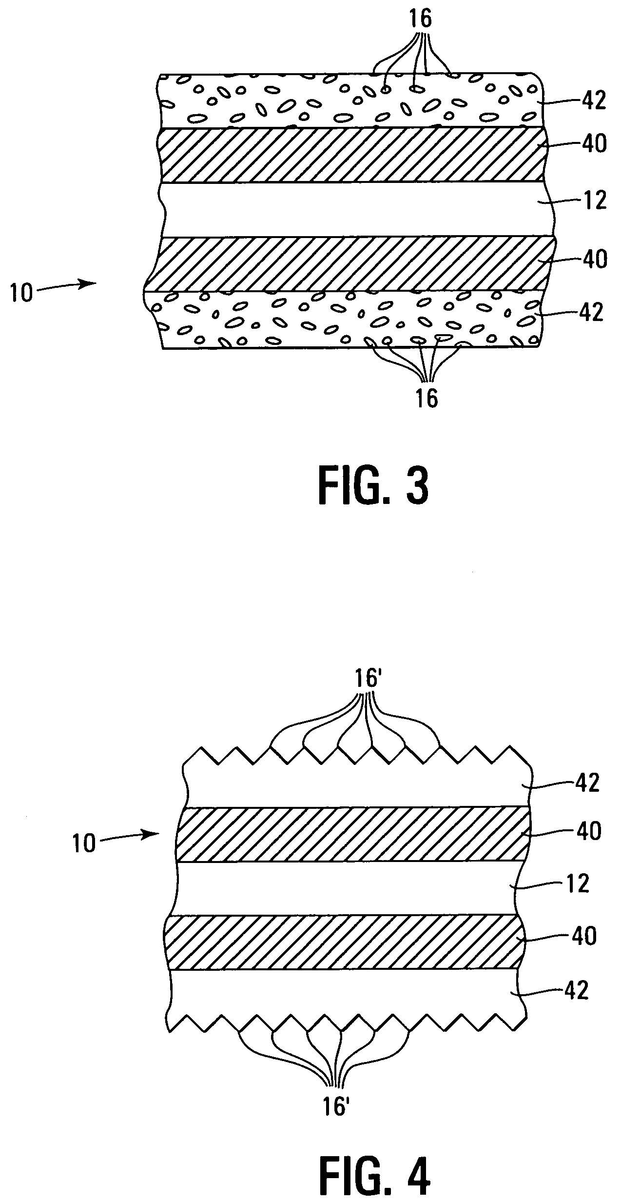
A method and a medium for laser imaging is herein disclosed. The medium incorporates one or more types of microstructures having a predetermined heat or radiation modifiable optical characteristic such as color, scattering, diffusion, diffraction, interference and iridescence. Associated intimately with the microstructures is a radiation antenna that acts to absorb radiation from a radiation source. The radiation antenna and source are attuned to one another to efficiently transfer energy therebetween and subsequently to the microstructures; this transfer of energy results in the modification of an optical characteristic of the microstructures to form an image on the medium. The medium has one or more layers that may include both the radiation antenna and the microstructures. Alternatively, the microstructures and radiation antenna may be included in separate layers. Coatings that incorporate one or more layers that include distinct microstructures and radiation antennae are also contemplated.

Description

TECHNICAL FIELD OF THE INVENTION[0001]The present invention relates to media and mechanisms for laser imaging. More particularly the present invention relates to media having a substrate that incorporates microstructures that may be readily altered to effect the formation of images thereon. The present invention also includes a printing mechanism for forming images on the aforementioned media.BACKGROUND OF THE INVENTION[0002]The use of microstructures in printable media is well known. Most such arrangements utilize reflective microstructures to provide an image, pattern, or color that changes with the angle at which the media is viewed. The microstructures in question generally function by diffraction, interference, scattering, diffusion, transmission or reflection of light of a preselected wavelength or by polarizing reflected light. Other methods and structures for producing an optically discernable image, pattern, or color using microstructures are also known.[0003]Generally, ima...

Claims


Application Information

Patent Timeline
Patent Type & Authority Patents(United States)
IPC IPC(8): G03E1/765G03C5/16G03F7/00G03F7/004
CPCB41M5/28B41M5/46Y10S430/165Y10S430/147B41M7/0081
Inventor KWASNY, DAVID MGORE, MAKARAND P.FIELD, MARSHALL
Owner HEWLETT PACKARD DEV CO LP
Learn More