Process for producing emulsion and microcapsules and apparatus therefor
a technology which is applied in the field of process and apparatus for producing emulsion and microcapsules, can solve the problems of low rate of preparing such microdroplets, inability to cover microdroplets with surfactants or microcapsule shells, etc., and achieves the effect of rapid production of emulsion and microcapsules in a simple manner
- Summary
- Abstract
- Description
- Claims
- Application Information
AI Technical Summary
Benefits of technology
Problems solved by technology
Method used
Image

Examples
first embodiment
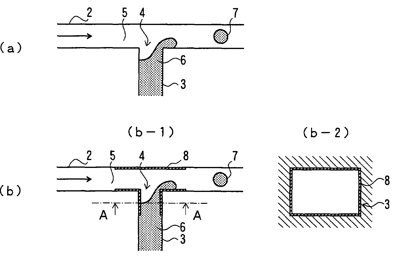
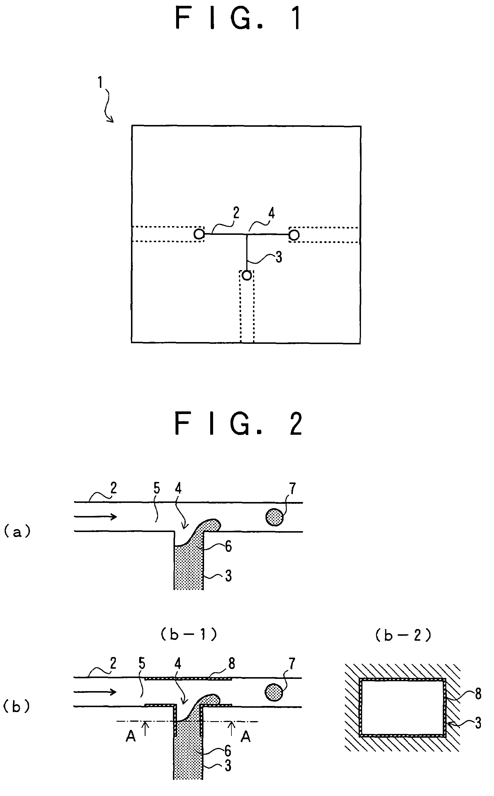
[0050]FIG. 1 is a plan view showing an apparatus for producing microdroplets according to the present invention, and FIG. 2 is an illustration showing processes for producing such microdroplets. FIG. 2(a) is an illustration showing a microdroplet-producing process (No. 1), FIG. 2(b) is another illustration showing a microdroplet-producing process (No. 2), FIG. 2(b-1) is a fragmentary sectional view thereof, and FIG. 2(b-2) is the sectional view of FIG. 2(b-1) taken along the line A-A.
[0051]In these figures, reference numeral 1 represents a main body of the microdroplet-producing apparatus, reference numeral 2 represents a microchannel in which a continuous phase flows and which is disposed in the main body 1, reference numeral 3 represents a dispersion phase-feeding channel placed such that the dispersion phase-feeding channel 3 and the microchannel 2 cross, reference numeral 4 represents a dispersion phase-feeding port, reference numeral 5 represents the continuous phase (for examp...
second embodiment
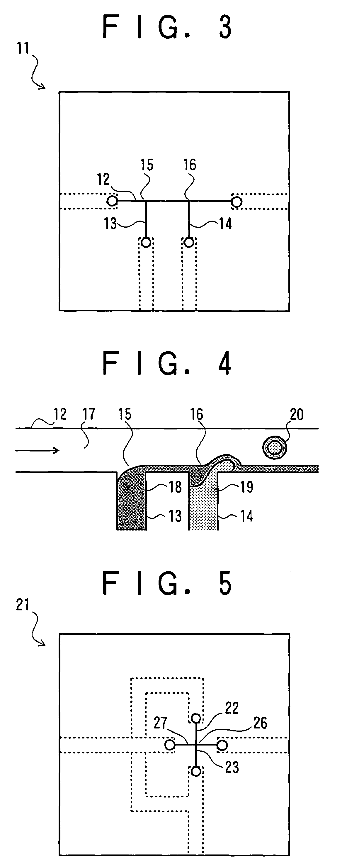
[0056]FIG. 3 is a plan view showing an apparatus for producing microcapsules and FIG. 4 is an illustration showing a process for producing such microcapsules.
[0057]In these figures, reference numeral 11 represents a main body of the microcapsule-producing apparatus, reference numeral 12 represents a microchannel in which a continuous phase flows and which is disposed in the main body 11, reference numeral 13 represents a shell-forming phase-feeding channel placed such that the shell-forming phase-feeding channel 13 and the microchannel 12 cross, reference numeral 14 represents a content-forming phase-feeding channel placed such that the content-forming phase-feeding channel 14 and the microchannel 12 cross, reference numeral 15 represents a shell-forming phase-feeding port, reference numeral 16 represents a content-forming phase-feeding port, reference numeral 17 represents the continuous phase (for example, water), reference numeral 18 represents a shell-forming phase, reference n...
third embodiment
[0059]FIG. 5 is a plan view showing an apparatus for producing microdroplets and FIG. 6 is an illustration showing a process for producing such microdroplets.
[0060]In these figures, reference numeral 21 represents a main body of the microdroplet-producing apparatus, reference numeral 22 represents a first microchannel, reference numeral 23 represents a second microchannel, reference numeral 24 represents a first continuous phase, reference numeral 25 represents a second continuous phase, reference numeral 26 represents the junction of flows of the first continuous phase 24 and the second continuous phase 25, reference numeral 27 represents a dispersion phase-feeding channel, reference numeral 28 represents a dispersion phase, and reference numeral 29 represents a microdroplet.
[0061]In the above configuration, the dispersion phase 28 is ejected toward the junction 26 of flows of the first continuous phase 24 and the second continuous phase 25 flowing in the microchannels 22 and 23, ...
PUM
| Property | Measurement | Unit |
|---|---|---|
| height | aaaaa | aaaaa |
| width | aaaaa | aaaaa |
| pressure | aaaaa | aaaaa |
Abstract
Description
Claims
Application Information
 - R&D
- Intellectual Property
- Life Sciences
- Materials
- Tech Scout
- Unparalleled Data Quality
- Higher Quality Content
- 60% Fewer Hallucinations
Browse by: Latest US Patents, China's latest patents, Technical Efficacy Thesaurus, Application Domain, Technology Topic, Popular Technical Reports.
© 2025 PatSnap. All rights reserved.Legal|Privacy policy|Modern Slavery Act Transparency Statement|Sitemap|About US| Contact US: help@patsnap.com