Circuits and methods for implementing approximations to logarithms

a technology of logarithms and approximations, applied in the field of computation methods, can solve the problems of additional processing time, cost of implementation as a circuit or integrated circuit, and inability to complete the calculation in time,

Inactive Publication Date: 2007-09-04
LOCKHEED MARTIN CORP
View PDF15 Cites 1 Cited by
  • Summary
  • Abstract
  • Description
  • Claims
  • Application Information

AI Technical Summary

Benefits of technology

[0013]Any means for obtaining, from the binary input, the integer part of the base 2 logarithm of the binary input can be used to replace the priority encoder. Those means could be a barrel shifter as in U.S. Pat. No. 5,831,878 or the circuit of U.S. Pat. No. 4,078,250. Since an algorithm exists for the integer part (as detailed in the preceding section), it is apparent that other means could be envisioned to implement the algorithm. However, in the embodiment of this invention in which means, other than the priority encoder, are used, it is not possible to ascertain that the circuit performs the approximation in one system clock time. Still, those embodiments comprise a fast and simple mantissa calculation.

Problems solved by technology

However, previously available methods and circuits either require multipliers, which would render the calculation slower, requiring more cycles of processing time, or require a large number of elements, which would render the implementation as a circuit or integrated circuit costly.
Approximating the mantissa requires more effort.
For many applications, such as those performing real time calculations and / or implementing the approximation for use with a digital signal processor (DSP), the use of multipliers can result in additional required cycles of processing time to complete the calculation.

Method used


Image

  • Circuits and methods for implementing approximations to logarithms
  • Circuits and methods for implementing approximations to logarithms
  • Circuits and methods for implementing approximations to logarithms

Examples


example 1

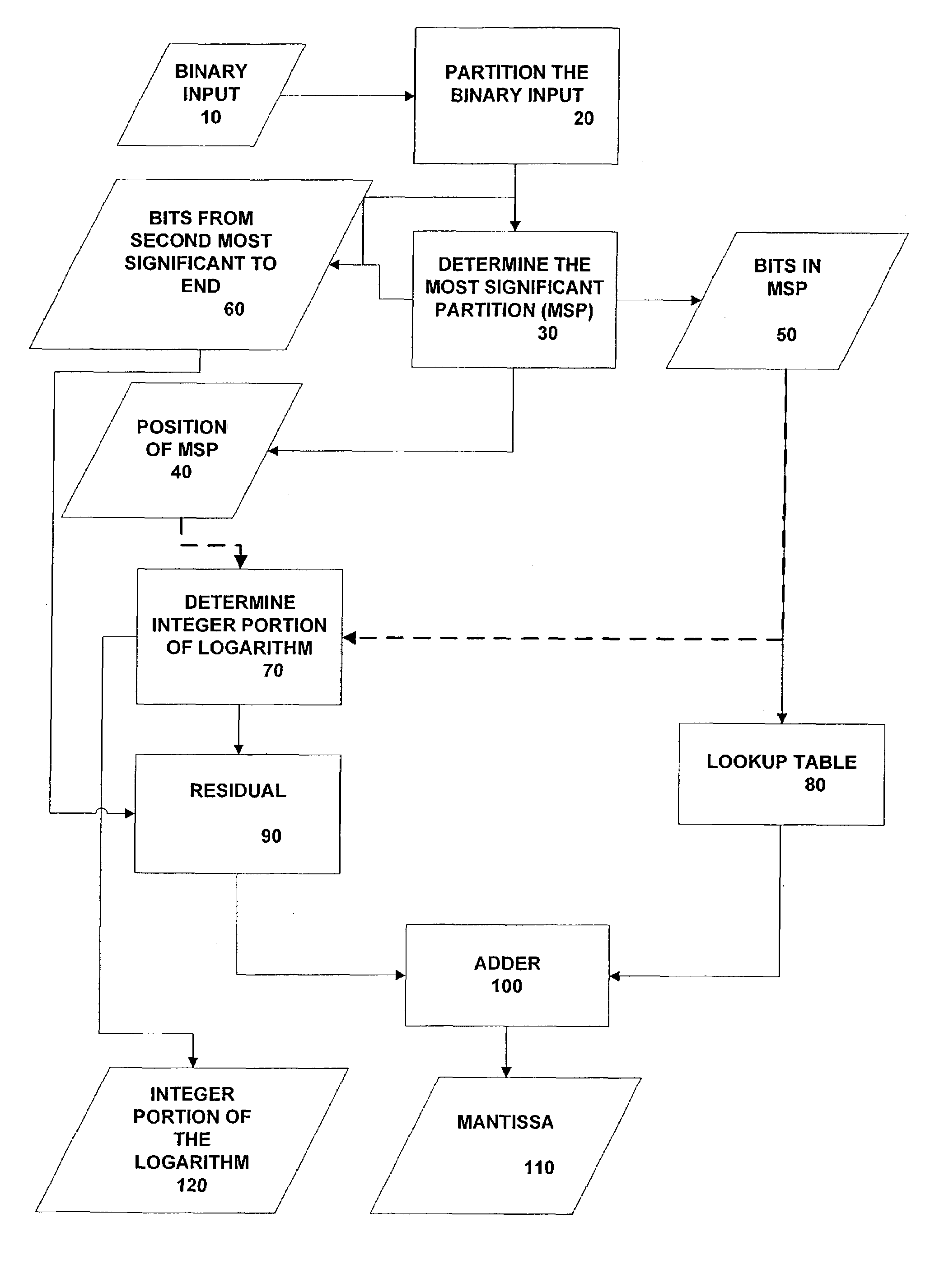
Binary Input is Hexadecimal 6700, which is binary 0110 0111 0000 0000.

In writing the binary number, it has already been partitioned into “nibbles”. The most significant nibble is nibble 3, thus, the first two bits in the integer portion, i3i2, are given by 11.

[0037]The most significant nibble is 0110. Then, bit 3 of the integer portion, i1 is given by

i1=0 OR 1=1.[0038]Bit 4 of the integer portion i0, is given by

i0n3 OR (NOT (n2) AND n1)=0 OR (NOT (1) and 1)=0.

The integer portion of the logarithm 220 of 6700 (Hex) is given by 1110.

[0039]The input to the lookup table is 6. This input yields

1 0 0 1 0 1 1 as output of the lookup table.

[0040]The portion of the binary number comprised of bits of the binary input up to a second most significant nibble 160 (Γ) is, from Table 2, given by 0 1 1 1 0 0 0.

[0041]Since the bit 1 and bit 0 of the integer portion are 1 0 respectively, according to Table 3, the divisor is 4 which results in a shift of 2 positions. The residual is then

[0042]

given by00...

example 2

(Illustrative of the Overflow)

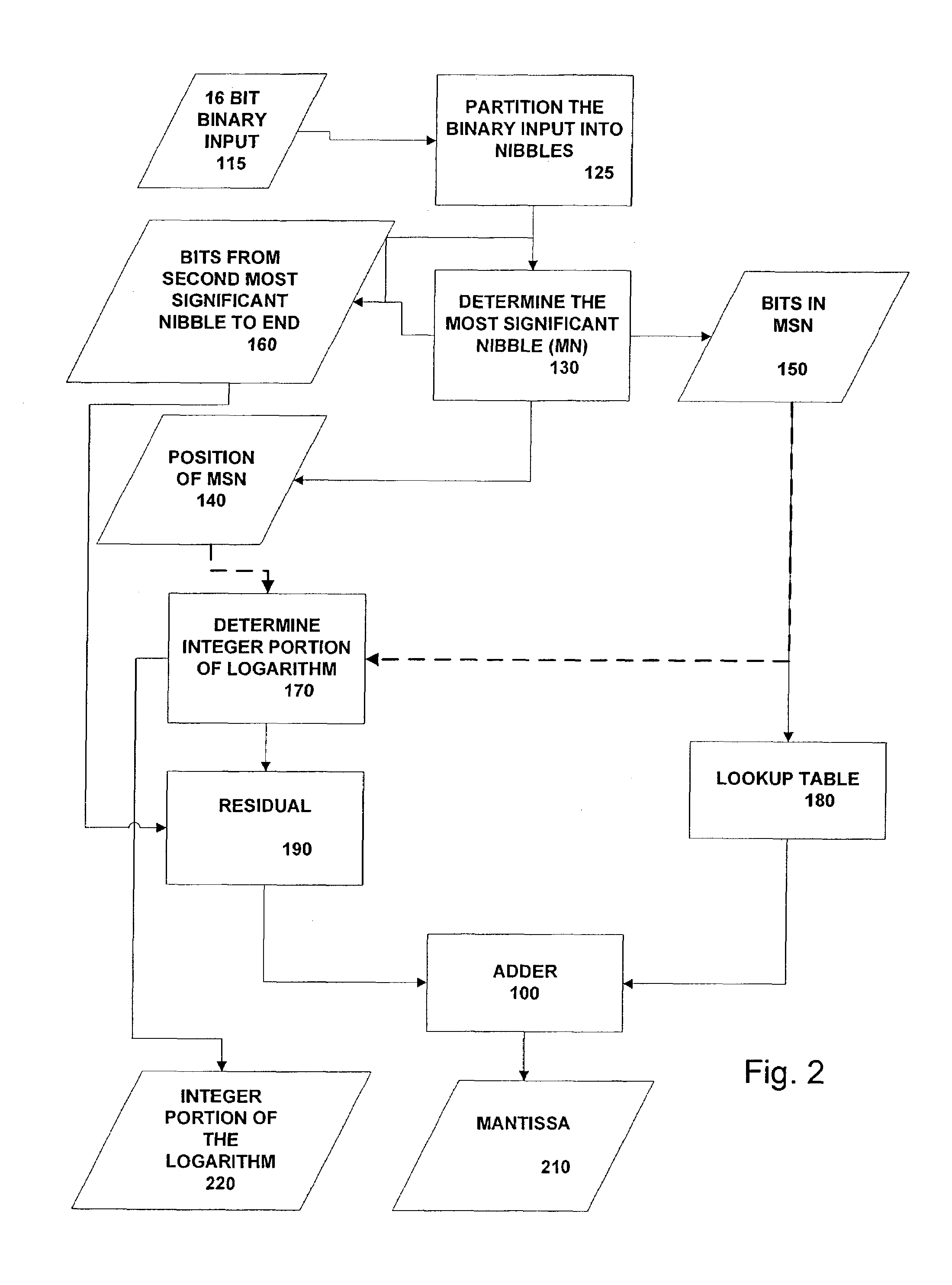
[0043]Binary Input is Hexadecimal 03F0, which is binary 0000 0011 1111 0000.

[0044]The most significant nibble is nibble 2, thus, the first two bits in the integer portion, i3i2, are given by 10.

[0045]The most significant nibble is 0011. Then, bit 3 of the integer portion, i1 is given by

i1=0 OR 0=0.[0046]Bit 4 of the integer portion i0, is given by

i0=n3 OR (NOT (n2) AND n1)=0 OR (NOT (0) and 1)=1.[0047]The integer portion of the logarithm 220 of 03F0 (Hex) is given by 1001.

[0048]The input to the lookup table is 3. This input yields 1 0 0 1 0 1 1 as output of the lookup table.

[0049]The portion of the binary number comprised of bits of the binary input up to a second most significant nibble 160 (Γ) is obtained by appending, to the second most significant nibble (1111), three bits from the nibble to the right of the second most significant nibble (as can be seen from Table 2), and is given by 1111000.

[0050]Since the bit 1 and bit 0 of the integer portion ar...


PUM


Abstract

A method for approximating a base 2 logarithm of a binary input and the circuit to implement the method are disclosed. The circuit comprises means for determining the integer portion of the logarithm, a lookup table module, a residual function module, an adder module and a register. This circuit performs the approximation in one system clock cycle time.

Description

STATEMENT OF GOVERNMENT INTEREST[0001]This invention was made partially with U.S. Government support from the Defense Advanced Research Administration (DARPA) and the United States Air Force (USAF) under contract No. F33615-98-C-1372. The U.S. Government has certain rights in the invention.BACKGROUND OF THE INVENTION[0002]This invention relates generally to circuits and computational methods for obtaining an approximation to a base 2 logarithm of a binary number and, more particularly, to a circuits and methods for a fast approximation implemented with few components or embedded gate resources.[0003]Logarithms appear in calculations in diverse fields ranging from audio to radar and also are used to facilitate computation. Due to the widespread use of logarithms in a calculation and computation, several methods and circuits have been proposed for approximating a logarithm of a binary input. However, previously available methods and circuits either require multipliers, which would ren...

Claims


Application Information

Patent Timeline
IPC IPC(8): G06F1/02G06F1/03G06F7/483G06F7/556
CPCG06F1/0307G06F7/556G06F7/483
Inventor GEORGE, RICHARD V.
Owner LOCKHEED MARTIN CORP
Why Eureka
Try Eureka