
Minimum miscible phase pressure computing method of low-permeability reservoir CO2 flooding

A technology of miscible pressure and calculation method, applied in the field of CO2 flooding, can solve the problems of low accuracy, large error and accuracy, and the theoretical formula calculation method is difficult to meet the calculation requirements of low permeability reservoirs.

Inactive Publication Date: 2018-07-10
CHINA PETROLEUM & CHEM CORP
View PDF4 Cites 13 Cited by
  • Summary
  • Abstract
  • Description
  • Claims
  • Application Information

AI Technical Summary

Problems solved by technology

[0004] The object of the invention is to provide a CO 2 Calculation method of minimum miscible pressure for flooding, to solve the problem of large experimental workload and strict sample requirements for the measurement of minimum miscible pressure by thin tube experiment method, and the calculation method of theoretical formula is difficult to meet the calculation requirements of low permeability reservoirs in Subei Basin, the theoretical basis is not strong, and the error is large The problem of low precision

Method used


Image

  • Minimum miscible phase pressure computing method of low-permeability reservoir CO2 flooding
  • Minimum miscible phase pressure computing method of low-permeability reservoir CO2 flooding
  • Minimum miscible phase pressure computing method of low-permeability reservoir CO2 flooding

Examples


Embodiment Construction

[0059] Preferred embodiments of the present invention will be described in detail below in conjunction with the accompanying drawings.

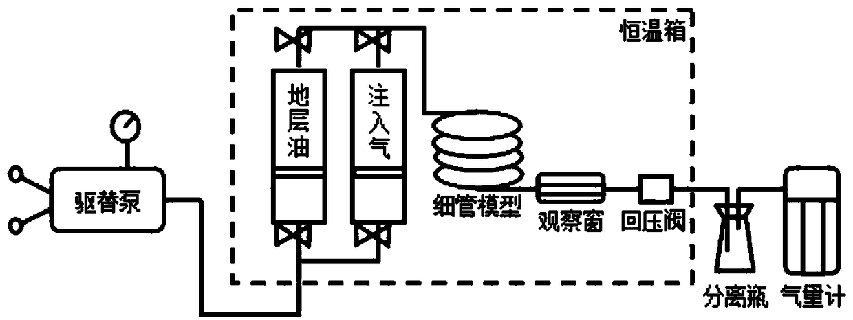
[0060] Example figure 1 , figure 2 and image 3 As shown, this embodiment provides a low permeability reservoir CO 2 Calculation method of minimum miscible pressure for flooding, including the following steps:

[0061] (1) Obtain the minimum miscible pressure and basic parameters of 5 samples by thin tube displacement experiment method;

[0062] (2) Calculate and obtain the minimum miscible pressure of the sample by substituting the basic parameters of 5 samples into the theoretical formula method;

[0063] (3) The minimum miscible pressure error of the same sample is obtained by comparing the thin tube displacement experiment method with the theoretical formula method, and four basic parameters of the sample are selected and substituted into the logarithmic formula (2):

[0064] LnPmm=lna+blnT+c(lnX vol -lnX int )+dlnMC 7+ ,

[006...


PUM


Abstract

The invention provides a minimum miscible phase pressure computing method of low-permeability reservoir CO2 flooding. The minimum miscible phase pressure computing method of low-permeability reservoirCO2 flooding comprises the following steps that minimum miscible phase pressure and underlying parameters of four or more samples are obtained by adopting a slim-tube displacement experimental method; the underlying parameters of the four or more samples are substituted through a theoretical formula method to calculate and obtain the minimum miscible phase pressure ; the minimum miscible phase pressure error of a same sample is obtained by comparing the slim-tube displacement experimental method and the theoretical formula method, and empirical constants are obtained by substituting the underlying parameters of four selected samples into a logarithm formula and establishing an augmented matrix; and a computational formula model is obtained by fitting the minimum miscible phase pressure ina low permeability reservoir and the underlying parameters. According to the minimum miscible phase pressure computing method of the low-permeability reservoir CO2 flooding, the minimum miscible pressure determined by the slim-tube displacement experimental method is more accurate, the theoretical formula method is more convenient and fast, and the cost is lower; at the same time, calculation requirements of the low-permeability reservoir in the Northern Jiangsu Basin can be met, a new derivation computational formula is more accurate in computational accuracy, the theoretical basis is higher, the labor intensity is low, and the minimum miscible pressure computing method of the low-permeability reservoir CO2 flooding is suitable for the use of low-permeability reservoir in the Northern Jiangsu Basin.

Description

technical field [0001] The present invention relates to CO 2 In the field of flooding technology, especially suitable for the deep buried, high formation temperature and heavy oil quality of low permeability reservoirs in northern Jiangsu 2 Calculation method of minimum miscibility pressure. Background technique [0002] Most of the Paleogene Paleocene Funing Formation and Taizhou Formation oil reservoirs in the Subei Basin are continental low-permeability reservoirs, and the reserves account for more than 80% of the total reserves. In addition to poor physical properties, they are also accompanied by strong water sensitivity characteristics , so water drive development is very difficult. CO 2 Miscible flooding has shown great potential in low-permeability reservoirs in Subei Basin, and is an important guarantee for stable and increased production in the next step. 2 Judging whether the reservoir can achieve miscibility is an important research content in flooding scheme...

Claims


Application Information

Patent Timeline
Patent Type & Authority Applications(China)
IPC IPC(8): E21B43/16E21B47/06E21B47/07
CPCE21B43/164E21B47/06E21B47/07
Inventor 郑永旺
Owner CHINA PETROLEUM & CHEM CORP
Learn More