
Systems and methods that facilitate motion control through coordinate system transformations

a technology of coordinate system and motion control, applied in the field of industrial control systems, can solve the problems of user modification, easy integration or user modification, and the conventional control system does not provide user-defined transformation, so as to facilitate user modification

Active Publication Date: 2007-09-04
ROCKWELL AUTOMATION TECH
View PDF18 Cites 19 Cited by
  • Summary
  • Abstract
  • Description
  • Claims
  • Application Information

AI Technical Summary

Benefits of technology

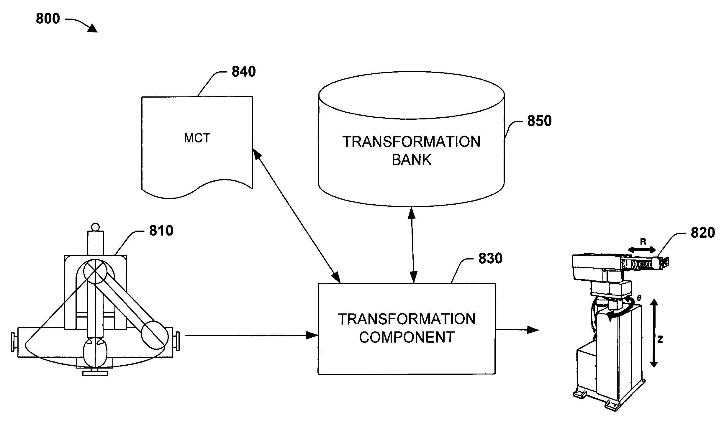
[0010]The subject invention relates to systems and methods that provide for multi-axis (e.g., multi-dimensional) motion coordination between different coordinate systems in the industrial control environment. The subject invention provides a set of pre-defined (system) transformations and enables a user to program / add user-defined transformations. Both pre-defined and user-defined transformations can be programmed in essentially any language including industrial control languages. This capability provides for novel advantages over conventional systems, which typically include coordinate system transforms that are hard coded in C, Basic, assembly, Pascal, and the like. Allowing user-defined transformations to be programmed in industrial control languages provides for seamless integration and synchronization of user-defined transformations with a control system, and facilitates ease of user modifications.

Problems solved by technology

However, conventional control systems either do not provide for user-defined transforms or such user-defined transforms are written in C, assembly, Pascal, Basic, and the like that are not easily integrated or user modified after being integrated within control software.

Method used


Image

  • Systems and methods that facilitate motion control through coordinate system transformations
  • Systems and methods that facilitate motion control through coordinate system transformations
  • Systems and methods that facilitate motion control through coordinate system transformations

Examples


Embodiment Construction

[0029]As utilized in this application, terms “component,”“system,”“controller,”“module,”“device,”“manager,” and variants thereof are intended to refer to a computer-related entity, either hardware, a combination of hardware and software, software, or software in execution. For example, a component may be, but is not limited to being, a process running on a processor, a processor, an object, an executable, a thread of execution, a program, and / or a computer. By way of illustration, both an application running on a server and the server can be a component. One or more components can reside within a process and / or thread of execution and a component can be localized on one computer and / or distributed between two or more computers.

[0030]As utilized herein, “transform,”“transformation,” and variants thereof generally refer to mapping (or converting) one or more coordinates in a coordinate system (e.g., related to a position in space) to one or more coordinates in another coordinate syste...


PUM


Abstract

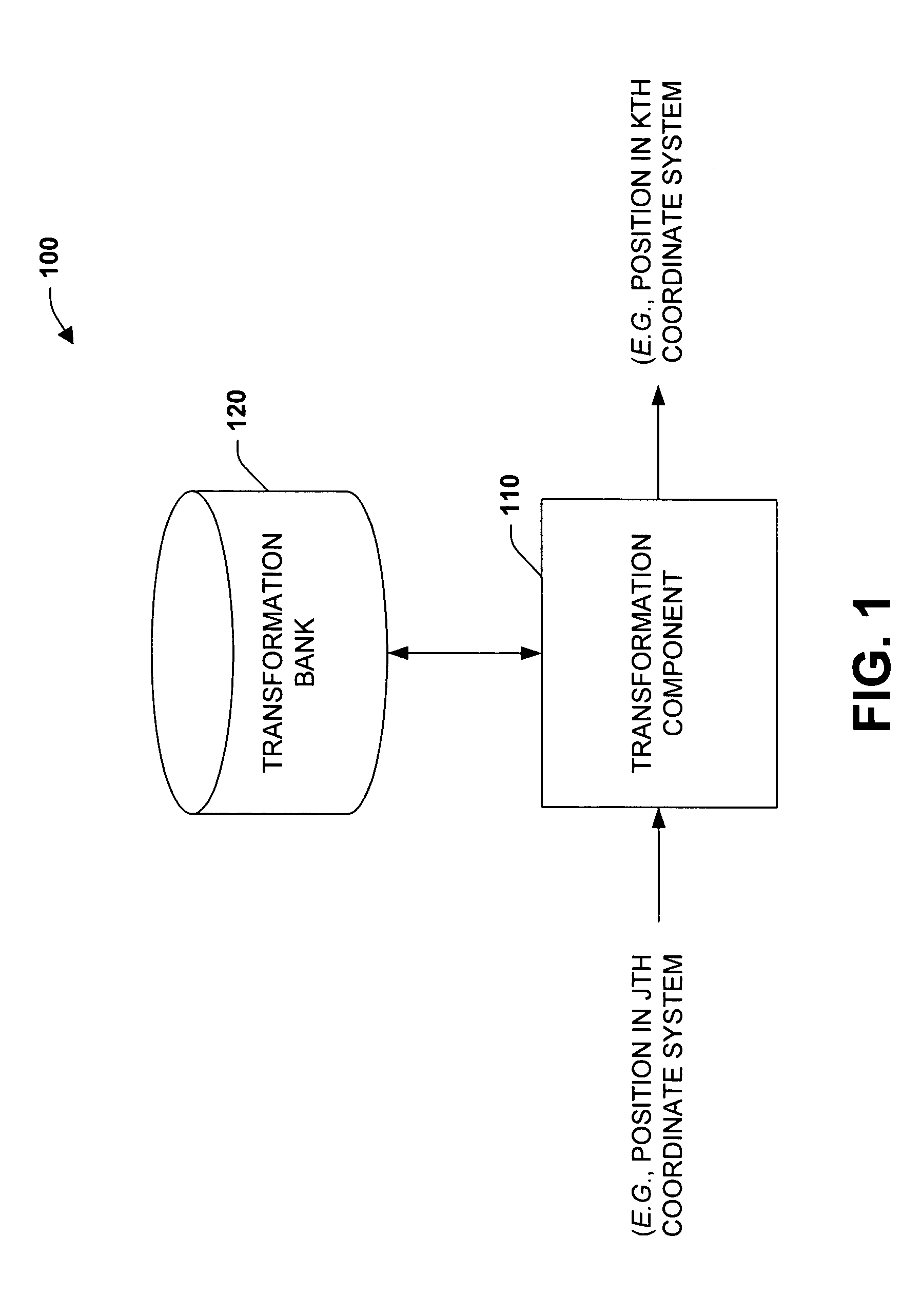
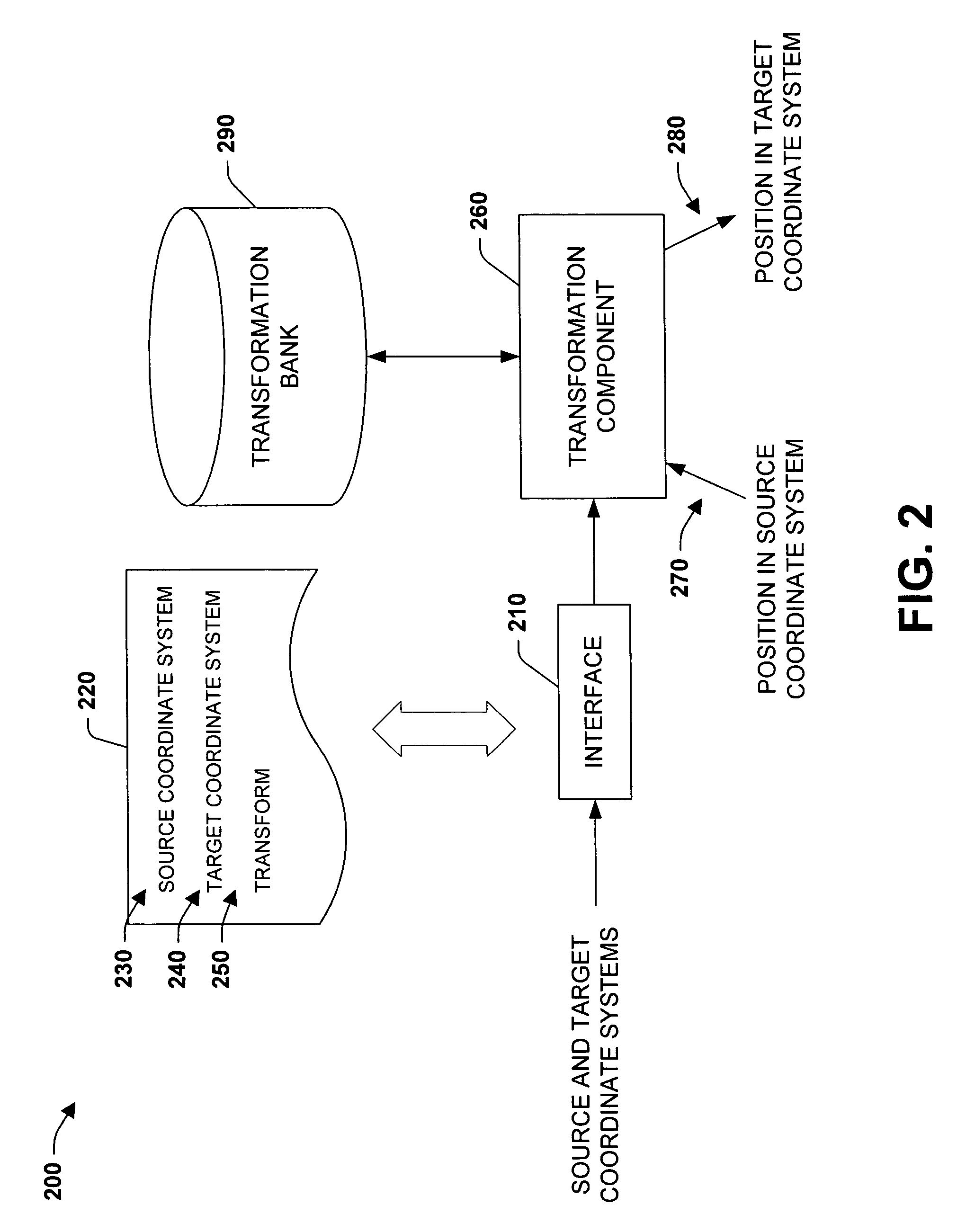
The subject invention relates to systems and methods that facilitate motion between different coordinate systems in an industrial control environment. The systems and methods accept data in one coordinate system and transform the data to a different coordinate system. Suitable transformations include instructions that transform between Cartesian, pre-defined non-Cartesian, and user-defined non-Cartesian coordinate systems, including transformations between a non-Cartesian coordinate system to another non-Cartesian coordinate system. Such transformations can be programmed in essentially any industrial control language and can be seamlessly integrated with the control environment. The systems and methods can be utilized to generate a motion instruction that includes, among other information, source and target coordinate systems and the transformation between them. The subject invention provides for connecting various systems together through respective motion instructions, wherein a motion of a source system is mapped to a coordinate system of a target system and the target system is moved accordingly.

Description

RELATED APPLICATIONS[0001]This application is related to co-pending U.S. patent application Ser. No. 10 / 838,472 filed on May 4, 2004 and entitled “SYSTEMS AND METHODS FOR INTEGRATED MULTI-AXIS COORDINATION” and to co-pending U.S. patent application Ser. No. 10 / 838,674 filed on May 25, 2004 and entitled “SYSTEMS AND METHODS FOR COORDINATION MOTION INSTRUCTIONS,” the entireties of these applications are incorporated herein by reference.TECHNICAL FIELD[0002]The subject invention relates to industrial control systems and, more particularly, to systems and methods that provide motion coordination between different coordinate systems through pre-defined and user-defined transforms written in industrial control languages.BACKGROUND OF THE INVENTION[0003]Industrial controllers are special purpose processing devices used for controlling (e.g., automated and semi-automated) industrial processes, machines, manufacturing equipment, plants, and the like. A typical controller executes a control p...

Claims


Application Information

Patent Timeline
Patent Type & Authority Patents(United States)
IPC IPC(8): G05B19/04G06F19/00G05B19/39
CPCB25J9/1658B25J9/1669G05B19/056G05B19/4086G05B2219/13106G05B2219/33263G05B2219/33269G05B2219/36038G05B2219/39139
Inventor BHATT, JATIN P.MALASPINA, FABIOPIATKA, MICHAELSCHWARZ, WILLIAM C.BROOKS, JEFFERY W.MILOSEVIC, SLOBODAN
Owner ROCKWELL AUTOMATION TECH
Learn More