
Optical disc apparatus and method of reproducing a wobble signal

a technology of optical discs and wobbles, applied in the field of optical disc apparatuses, can solve the problems of reducing the capacity of optical discs, affecting the reproduction efficiency of optical discs, so as to prevent the degraded signal of the reproduced wobbl

Inactive Publication Date: 2007-09-04
SAMSUNG ELECTRONICS CO LTD
View PDF11 Cites 23 Cited by
  • Summary
  • Abstract
  • Description
  • Claims
  • Application Information

AI Technical Summary

Benefits of technology

[0013]Accordingly, it is an object of the present invention to provide an optical disc apparatus and a wobble signal reproducing method, capable of preventing a reproduced wobble signal from being degraded due to an interference from the wobbles of adjacent tracks during reproduction of a wobble signal from an optical disc manufactured by a wobble modulation manner.

Problems solved by technology

Recording address information on uneven pre-pits formed in the header area reduces the capacity of an optical disc.
In addition, the above-described address information recording technique is bad in the aspect of compatibility with reproduction-dedicated optical discs.
However, in a conventional wobble signal reproduction manner using a radial push-pull signal, if the track pitch is narrowed to increase the recording density of an optical disc, an interference (cross-talk) due to wobbles of adjacent tracks degrades the signal-to-noise (S / N) ratio of a reproduced wobble signal.
This hinders accurate restoration of address information.

Method used


Image

  • Optical disc apparatus and method of reproducing a wobble signal
  • Optical disc apparatus and method of reproducing a wobble signal
  • Optical disc apparatus and method of reproducing a wobble signal

Examples


Embodiment Construction

[0042]Reference will now be made in detail to the embodiments of the present invention, examples of which are illustrated in the accompanying drawings, wherein like reference numerals refer to like elements throughout. The embodiments are described below in order to explain the present invention by referring to the figures.

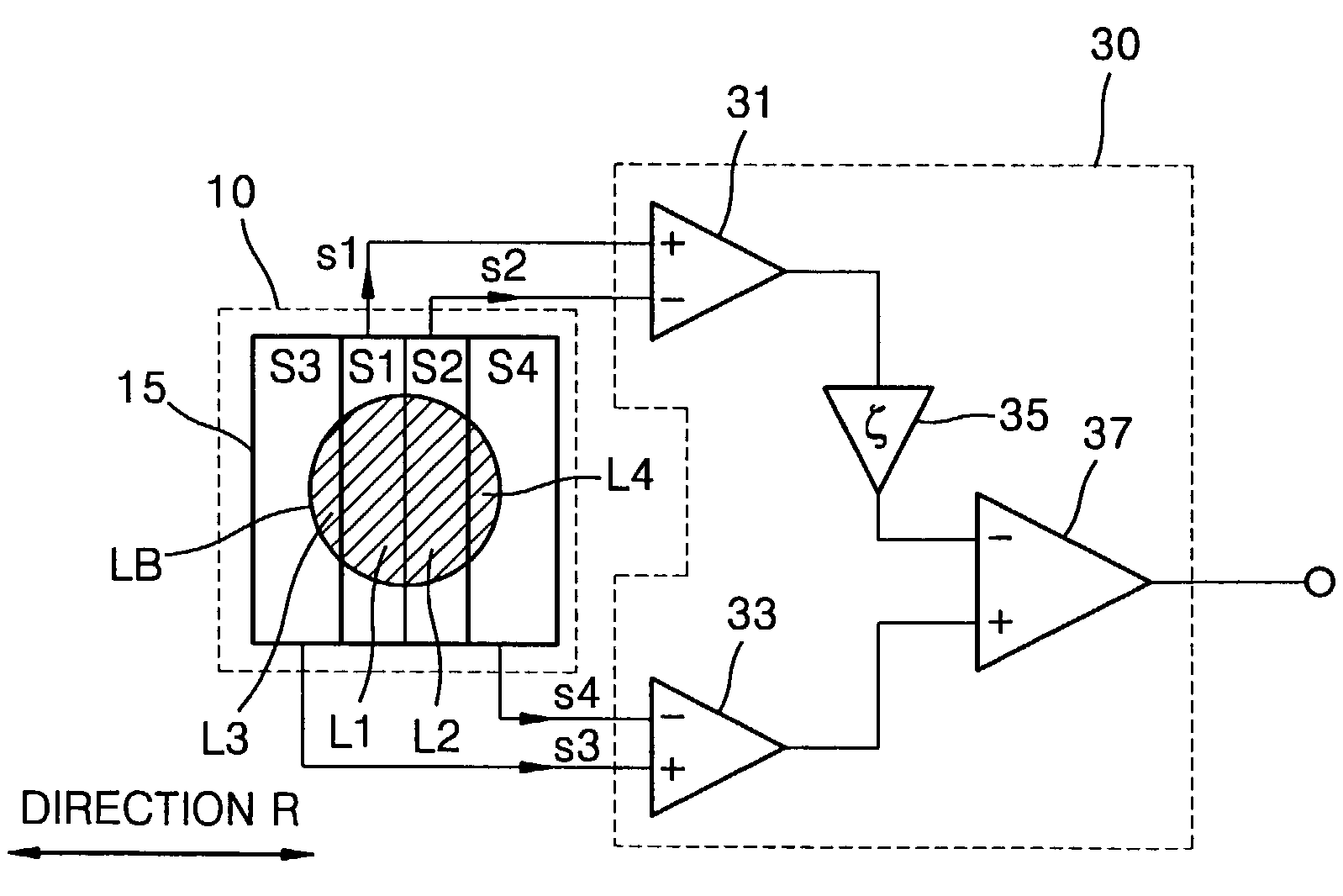
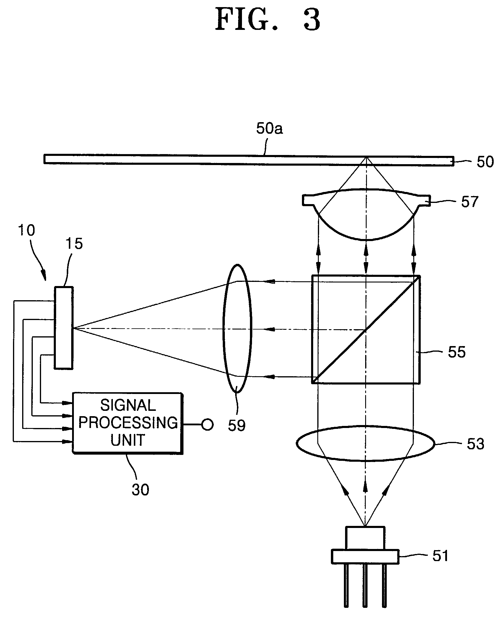
[0043]FIG. 2 is a schematic view of an optical disc apparatus according to an embodiment of the present invention. FIGS. 3 and 4 show examples of an optical pickup applicable to an optical disc apparatus according to the present invention.

[0044]Referring to FIG. 2, an optical disc apparatus according to the present invention comprises a light division and / or detection device 10 and a signal processing unit 30. The light division and / or detection device 10 divides a light beam (LB) projected onto an optical disc and reflected by it into at least four regions in a direction corresponding to the radial direction of the optical disc (hereinafter, the direction is refe...


PUM


Abstract

An optical disc apparatus and a wobble signal detection method in which a light beam projected onto an optical disc and reflected by the optical disc is divided into at least four light regions in the direction corresponding to the radial direction of the optical disc to detect the light regions, and a wobble signal is detected by performing a subtraction on first and second difference signals, the first difference signal obtained by performing a subtraction on detection signals for the inner light regions of the divided and / or detected light beam and the second difference signal obtained by performing a subtraction on detection signals for the outer light regions of the divided and / or detected light beam. Accordingly, when a wobble signal is reproduced from an optical disc manufactured by a wobble modulation manner, a wobble signal is prevented from being degraded due to the interference (cross talk) from the wobbles of adjacent tracks, even though the track pitch of the optical disc is reduced to improve the recording density.

Description

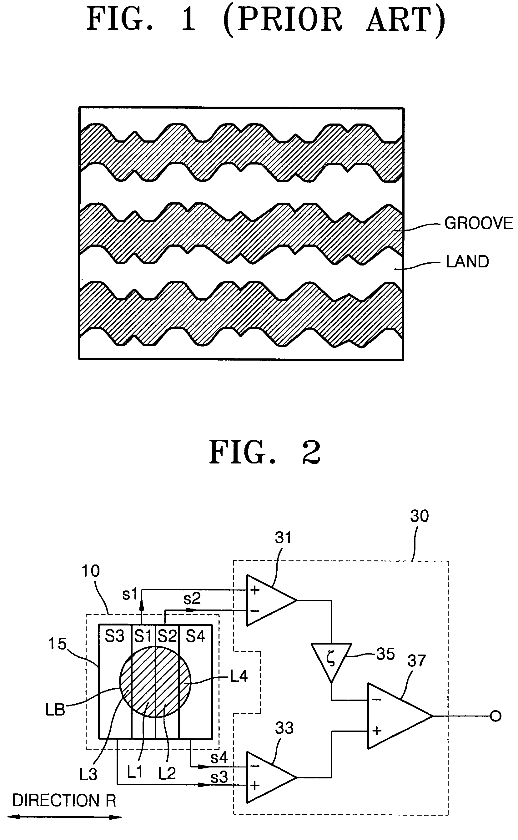
CROSS-REFERENCE TO RELATED APPLICATIONS[0001]This application claims the benefit of Korean Application No. 2001-38803, filed Jun. 30, 2001, in the Korean Industrial Property Office, the disclosure of which is incorporated herein by reference.BACKGROUND OF THE INVENTION[0002]1. Field of the Invention[0003]The present invention relates to the field of optical disc apparatuses, and more particularly, to an optical disc apparatus capable of reproducing a wobble signal from an optical disc manufactured by wobble modulation and to a method of reproducing a wobble signal.[0004]2. Description of the Related Art[0005]Recordable optical discs, such as CD-R / RW, DVD-RAM, DVD-R / RW or DVD+RW optical discs, have guide grooves formed along tracks in order to help an optical pickup to follow a desired track exactly. The guide grooves are referred to as grooves, and the remaining portions are referred to as lands. Recordable discs are classified into optical discs to record user data on only either o...

Claims


Application Information

Patent Timeline
IPC IPC(8): G11B7/005G11B7/007G11B7/13G11B19/02G11B7/131G11B7/135G11B7/1381G11B20/14G11B27/19G11B27/24G11B27/30
CPCG11B7/0053G11B7/131G11B7/1381G11B7/24082G11B27/24G11B20/1403G11B27/3027G11B2220/216G11B2220/218G11B2220/2545G11B2220/2562G11B19/02
Inventor KIM, TAE-KYUNGAHN, YOUNG-MANKIM, JONG-BAELEE, JIN-KYUNGCHUNG, CHONG-SAM
Owner SAMSUNG ELECTRONICS CO LTD
Learn More