
Antenna device

a technology of antenna and antenna body, which is applied in the direction of antenna details, antenna adaptation in movable bodies, antennas, etc., can solve the problems of unfavorable antenna installation, unnecessary force (stress) on the antenna, and cracks in the solder

Inactive Publication Date: 2007-09-04
KK TOKAI RIKA DENKI SEISAKUSHO +1
View PDF5 Cites 5 Cited by
  • Summary
  • Abstract
  • Description
  • Claims
  • Application Information

AI Technical Summary

Benefits of technology

The design maintains the connection between the antenna and base plate without unnecessary stress, preventing deformation and solder cracks, while allowing for easy solder application and precise connection, effectively regulating the positional relationship between the antenna and base plate.

Problems solved by technology

Here, when the antenna and the circuit board are attached to the inside of the case, error arises in the relative positional relationship between the antenna and the circuit board inside the case due to error in the position of the retaining protrusion and screwed portion inside the case, dimensional error of the antenna, and error in the positions of a hole formed in the circuit board in order to insert a screw when the circuit board is screwed to the case.
Unnecessary force (stress) acts on the antenna when such error arises because the base end side of the antenna is fixed to the circuit board with solder.
Further, when tension or the like acts on the solder connecting the antenna and the circuit board due to such error, cracks arise in the solder.

Method used


Image

  • Antenna device
  • Antenna device
  • Antenna device

Examples


Embodiment Construction

CONFIGURATION OF THE EMBODIMENT

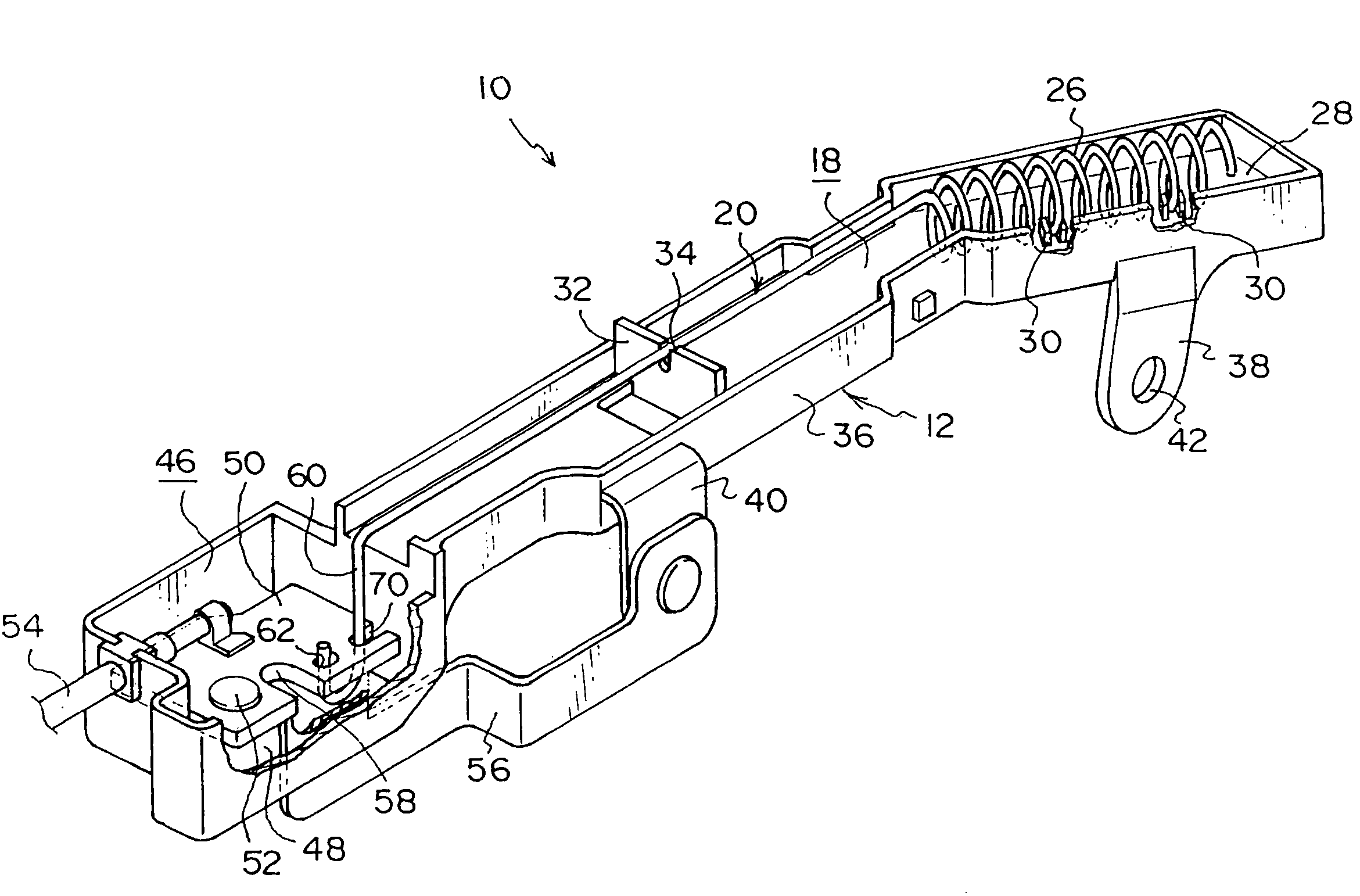
[0041]The relevant portions of an antenna device 10 pertaining to an embodiment of the invention are shown in perspective view in FIG. 1.

[0042]As shown in FIG. 1, the antenna device 10 includes a case 12. As shown in FIG. 4, the case 12 is disposed inside a visor 16 of a door mirror 14. As shown in FIG. 1, the case 12 includes an antenna housing 18.

[0043]The antenna housing 18 is formed in a narrow box-like shape that opens substantially upward in a state where the case 12 is disposed inside the visor 16. An antenna 20 is housed inside the antenna housing 18. The antenna 20 is formed by a metal rod-like member that is long along the longitudinal direction of the antenna housing 18.

[0044]The leading end side of the antenna 20 from its intermediate portion in the longitudinal direction serves as a body portion 26. The body portion 26 is formed as a coil whose axial direction is a direction inclined substantially downward with respect to the longitudinal ...


PUM


Abstract

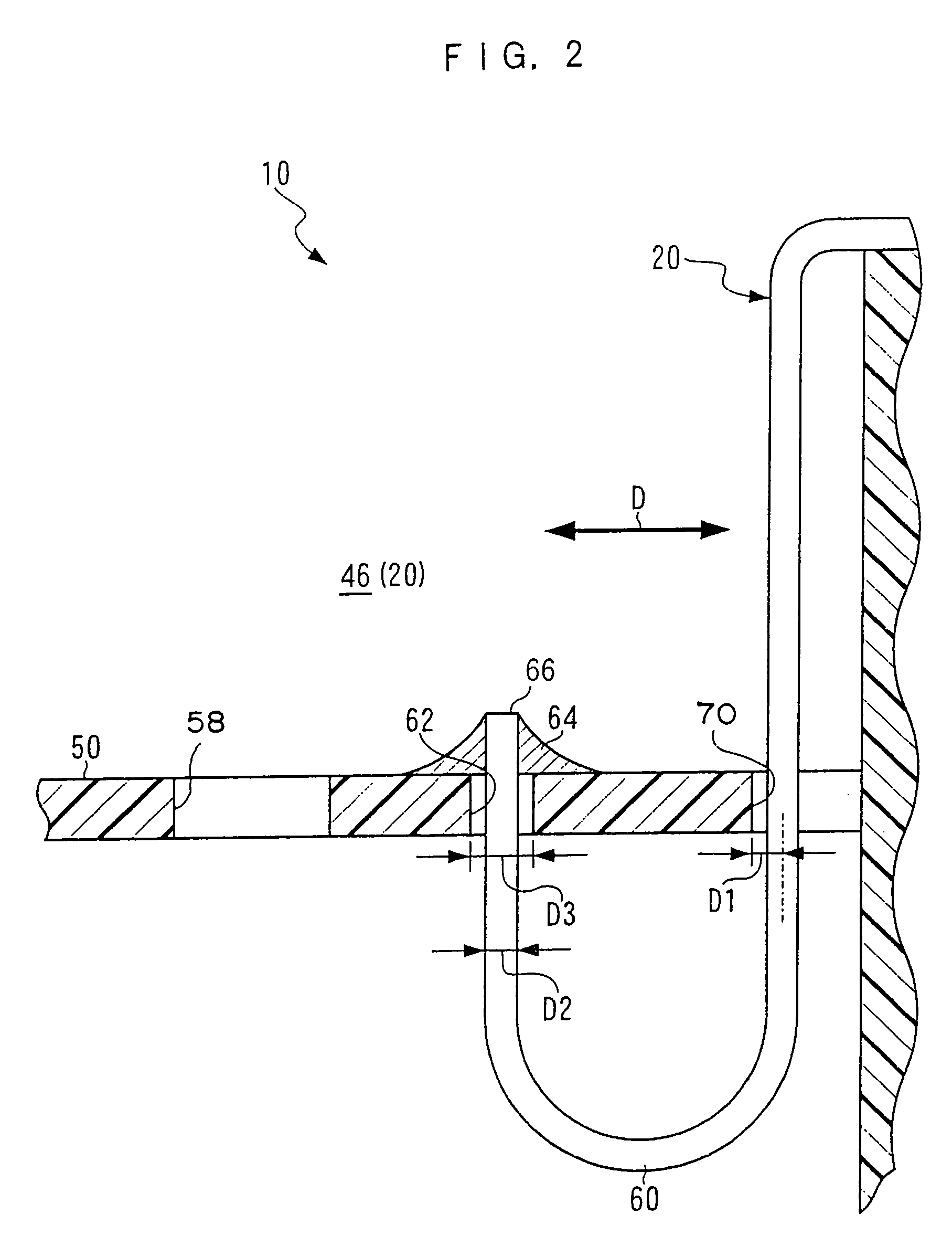
A cutout portion through which one end side of a U-shaped portion of the antenna passes is cut deeper than a preset passing position where the U-shaped portion passes through the cutout portion. Further, an open dimension of a through hole through which the other end side of the U-shaped portion passes is substantially twice an outer diameter dimension of the U-shaped portion. When the U-shaped portion is passed through the through hole at the preset passing position, the U-shaped portion passes through the substantial center of the through hole. When error arises in the retention position of the antenna and the fixing position of the base plate, the U-shaped portion is displaced inside the cutout portion and the through hole, and the above error is absorbed.

Description

CROSS-REFERENCE TO RELATED APPLICATION[0001]This application claims priority under 35 USC 119 from Japanese Patent Application No. 2005-86703, the disclosure of which is incorporated by reference herein.BACKGROUND OF THE INVENTION[0002]1. Field of the Invention[0003]The present invention relates to an antenna device that transmits or receives radio waves with an antenna.[0004]2. Description of the Related Art[0005]For example, in the tire pressure monitoring system (TPMS) disclosed in Japanese Patent Application Publication (JP-A) No. 11-254925, the air pressure of tires is detected by detecting means disposed inside the tires. An electrical signal corresponding to the detection result is outputted from the detecting means, and a wireless signal corresponding to the level of the electrical signal is outputted from transmitting means.[0006]The wireless signal outputted from the transmitting means is received by receiving means, and an electrical signal corresponding to the level of t...

Claims


Application Information

Patent Timeline
Patent Type & Authority Patents(United States)
IPC IPC(8): H01Q1/32
CPCH01Q1/3266H01Q9/40H01Q9/42
Inventor NAKAJIMA, NANAKOJIMA, HIROAKI
Owner KK TOKAI RIKA DENKI SEISAKUSHO
Learn More