Controllable microscopic bubble nucleation in fluid polymer material production method and its apparatus

a technology of fluid polymer and microscopic bubbles, which is applied in the direction of dough homogenization, dough mixing/kneading machines, baking, etc., can solve the problems of high cost of foaming material, difficult control of separation, and high cost. , to achieve the effect of increasing equipment costs and malfunctioning rates

Inactive Publication Date: 2007-09-04
EVERFOCUS WORLDWIDE
View PDF2 Cites 12 Cited by
  • Summary
  • Abstract
  • Description
  • Claims
  • Application Information

AI Technical Summary

Benefits of technology

[0006]2. The deposition opening of the said foaming agent is situated at the outer edge of the materials pipe and is in continuity with the blending section of the conveyance screw shaft and, furthermore, adding in occurs at a set point, the foaming agent and liquid polymer material then blended and amalgamated by the conveyance screw shaft at the materials pipe section; however, before the liquid polymer material is blended, the foaming agent is introduced onto the surface of the melted polymer material and then blended, easily causing bubble run off and unevenness; furthermore, foaming agent and polymer material blending involves a lengthy foaming period and a slow rate that correspondingly increases cost.
[0009]1. The invention herein utilizes a microbubble generating component (such as a microscopic perforation vented metal head or a microscopic perforation ceramic head, etc.) installed on a conveyance screw shaft and, furthermore, the said gas pipe is disposed in the interior section of the conveyance screw shaft and connected to the said microbubble generating component (such as a microscopic perforation vented metal head or a microscopic perforation ceramic head, etc.), enabling the delivery of gas through the gas pipe via a pressurization pump or a high pressure gas storage tank, with a heater at the outer edge of a materials pipe melting a polymer material, while indirectly pre-heating the gas pipe, such that microscopic bubbles are then outputted from the inside of irregularly arranged microscopic perforations of the microbubble generating component (such as a microscopic perforation vented metal head or a microscopic perforation ceramic head, etc.) which are widely distributed directly into the interior portion of the liquid polymer material, simultaneously blended and transferred by the conveyance screw shaft, and next injected into a forming die for lowering to critical temperature and pressure reduction as the polymer material is microbubble nucleated, thereby providing for simultaneous microbubble generation, blending, and transference to achieve the even distribution of microbubbles in the polymer material and, furthermore, the said microbubble nucleation dimensions are based on that of the microscopic perforations of the microbubble generating component 18 (such as a microscopic perforation vented metal head or a microscopic perforation ceramic head, etc.) to achieve the required size of less than 35 microns.
[0010]2. The invention herein utilizes a microbubble generating component (such as a microscopic perforation vented metal head or a microscopic perforation ceramic head, etc.) installed at the front extremity of the conveyance screw shaft such that the said microscopic bubble supply section can be controlled to supply intermittently, enabling a clear demarcation of nucleated and non-nucleated polymer material injected into the forming die and, furthermore, the present invention is easy to control and further provides for adhesion of the non-nucleated polymer to the forming die surface, the said non-nucleated polymer material surrounding the microbubble nucleated polymer material at the interior section to thereby achieve a non-porous glossy surface encapsulating a microbubble nucleated interior section.
[0011]3. Since the microscopic perforations of the microbubble generating component in the invention herein are irregularly arranged outwardly from the inside, the polymer material does not have to flow into the microscopic perforations and, furthermore, clogging is precluded because the said conveyance screw shaft is at high temperature and melts the polymer material into liquid, with the microscopic bubbles forced out at high pressure such that a check valve is not required, reducing equipment cost and lowering malfunction rates.

Problems solved by technology

1. The polymer material nucleation obtained by the prior art polymer material nucleation method is incapable of a microscopic cell perforation dimensions of less than 35 microns using only a gaseous, liquid, or solid foaming agent because the bubbles produced are not uniform; a micron foaming material is required for such uniformity.
However, the said micron foaming material is expensive high in cost, and offers little economic advantage.2. The deposition opening of the said foaming agent is situated at the outer edge of the materials pipe and is in continuity with the blending section of the conveyance screw shaft and, furthermore, adding in occurs at a set point, the foaming agent and liquid polymer material then blended and amalgamated by the conveyance screw shaft at the materials pipe section; however, before the liquid polymer material is blended, the foaming agent is introduced onto the surface of the melted polymer material and then blended, easily causing bubble run off and unevenness; furthermore, foaming agent and polymer material blending involves a lengthy foaming period and a slow rate that correspondingly increases cost.3. Heating in the materials pipe to melt the liquid polymer material, it is difficult to control the separation of the non-nucleated portion and nucleated portion at injection into the forming die and, furthermore, control over the required foaming agent percentage with the non-nucleated section is very problematic.4. A check valve must be installed at the said foaming agent deposition opening to prevent polymer material counter flow, but the device increases equipment costs and malfunction rates.

Method used


Image

  • Controllable microscopic bubble nucleation in fluid polymer material production method and its apparatus
  • Controllable microscopic bubble nucleation in fluid polymer material production method and its apparatus
  • Controllable microscopic bubble nucleation in fluid polymer material production method and its apparatus

Examples


first embodiment

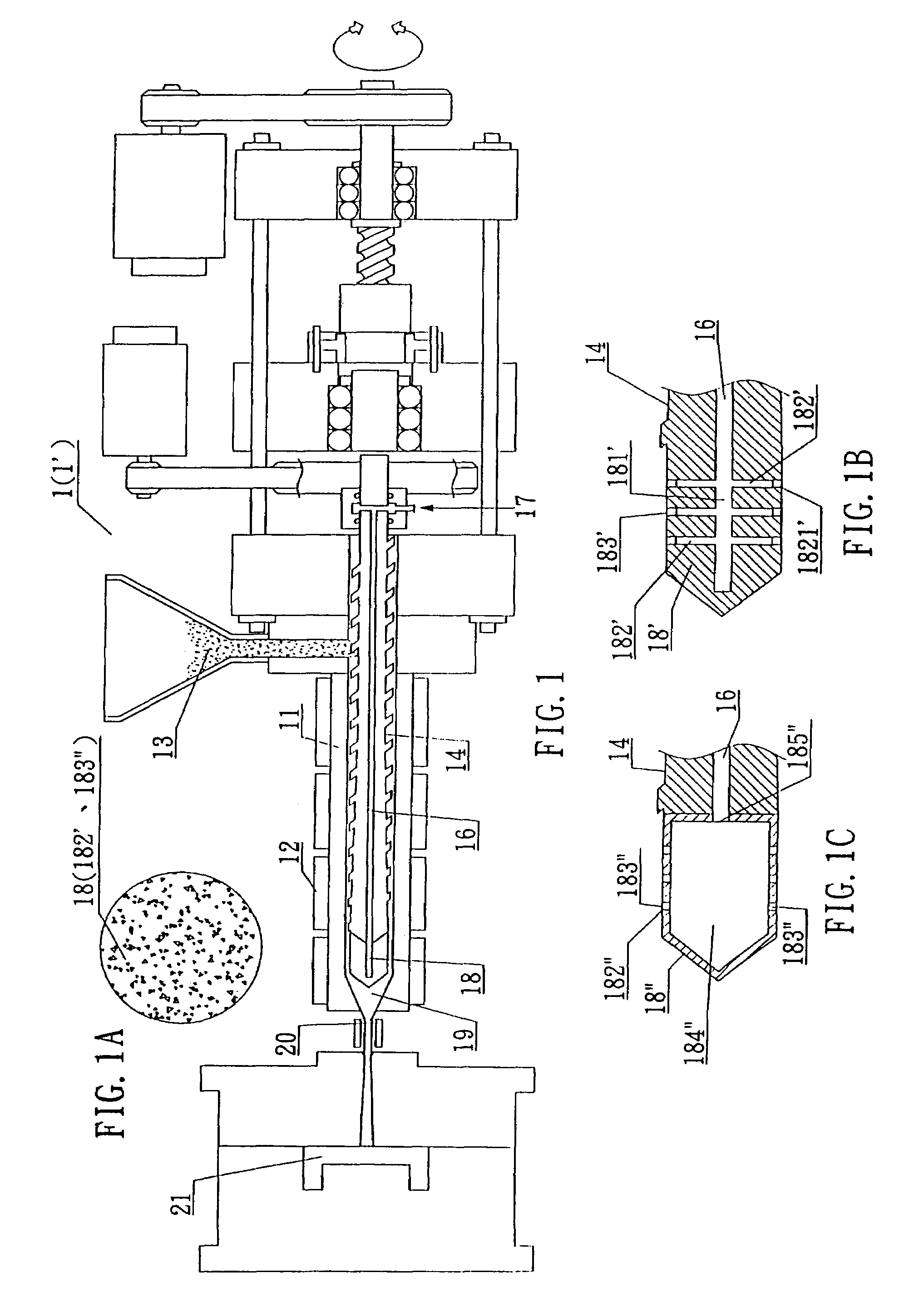
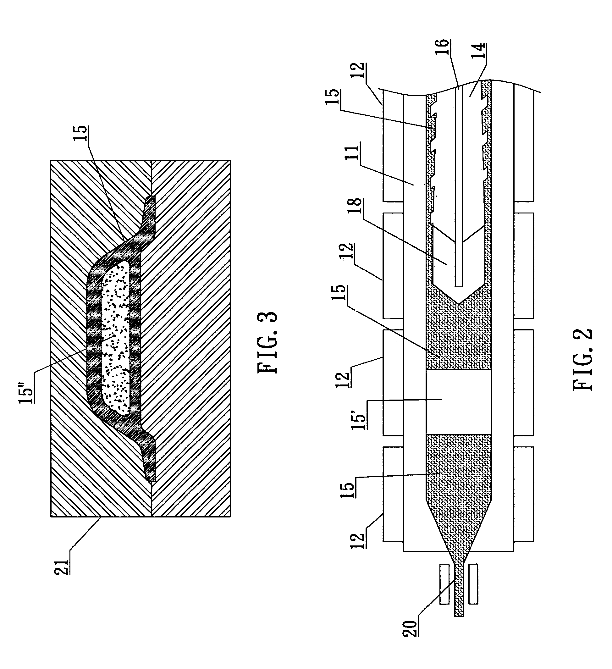
[0024]the invention herein, referring to FIG. 1 and FIG. 1-A, utilizes a materials pipe 11 inside an injector or an extractor 1 (1′) having a heater 12 outside to melt polymer material 13 which is transferred and blended along a conveyance screw shaft 14, the molten liquid polymer material 15 thereby pushed forward; the said foaming source utilized involves the gaseous precipitation of a foaming reaction in the polymer material; a gas pipe 16 is disposed in the conveyance screw shaft 14, an air intake opening 17 is situated at the rear extremity and connected to a pressurization pump or a high pressure gas storage tank and, furthermore, a microbubble generating component 18 (such as a microscopic perforation vented metal head or a microscopic perforation ceramic head, etc.) is installed at the front extremity of the conveyance screw shaft 14; the said microbubble generating component 18 (such as a microscopic perforation vented metal head or a microscopic perforation ceramic head, e...

fourth embodiment

[0030]the invention herein, referring to FIG. 5-A, FIG. 5-B, and FIG. 5-C, consists of an apparatus in which when the extractor is utilized to draw out the polymer material, the non-nucleated is maintained at the outer portion of the said extracted polymer material so that the surface is glossy and the nucleated is generated at the inner portion; a flow diverter ring 22 is sleeved onto the front end of the microbubble generating component 18 and ribs 221 are formed lengthwise along the outer edges of the said flow diverter ring 22 such that the height between the outer edges of the flow diverter ring 22 and the materials pipe 11 defined by the lengthwise ribs 221 form a non-microbubble permeated polymer material channel 222, while that between the inner edge of the flow diverter ring 22 and the microbubble generating component 18 form a microbubble permeated polymer material channel 223; as a result, referring to FIG. 5-C and FIG. 6, the said liquid polymer material 15 is pushed for...


PUM

PropertyMeasurementUnit
sizeaaaaaaaaaa
pressureaaaaaaaaaa
heightaaaaaaaaaa

Abstract

A controllable microscopic bubble nucleation in fluid polymer material production method and apparatus utilizing a gas pipe disposed in the conveyance screw shaft of an injection or extraction forming mechanism and a microbubble generating component, such as a microscopic perforation vented metal head or a microscopic perforation ceramic head, installed at the front extremity of the conveyance screw shaft. At the rear extremity of the gas pipe, a pressurization pump or a high pressure gas storage tank is admitted from an air intake opening, enabling the gas to be indirectly heated by an electric heater on the materials pipe. The high temperature gas is thereafter outputted from the microscopic perforations of the microbubble generating component such that high temperature microscopic bubbles are directly admitted into the section of liquid polymer material which is then uniformly amalgamated by the conveyance screw shaft and then deposited into a forming die.

Description

BACKGROUND OF THE INVENTION[0001]1) Field of the Invention[0002]The invention herein relates to a controllable microscopic bubble nucleation in fluid polymer material production method and its apparatus consisting of a heater installed around a conveyance screw shaft that melts polymer material in a materials pipe, a gas pipe disposed in the conveyance screw shaft and, furthermore, a microbubble generating component (such as a microscopic perforation vented metal head or a microscopic perforation ceramic head, etc.) connected to the front extremity of the conveyance screw shaft, wherein by controlling whether the high pressure gas of a pressurization pump or a high pressure gas storage tank is transferred affords control over forming sections of liquid polymer material into the bubble nucleated or the non-bubble nucleated.[0003]2) Description of the Prior Art[0004]The polymer material utilized by conventional injection or extraction forming mechanisms is melted into a liquid, follow...

Claims


Application Information

Patent Timeline
Patent Type & Authority Patents(United States)
IPC IPC(8): B29C44/20B29C44/34B29C39/10
CPCB29C44/3446B29C44/3449B29C44/3469
Inventor CHANG, CHIEN-TSUNGHIND, DAVID WILLIAM
Owner EVERFOCUS WORLDWIDE
Why Eureka
Try Eureka