
Edgewise orthodontic bracket for capturing lost torque

Inactive Publication Date: 2007-09-04
IMPACT RES
View PDF8 Cites 15 Cited by
  • Summary
  • Abstract
  • Description
  • Claims
  • Application Information

AI Technical Summary

Benefits of technology

[0036]This small amount of over tipping is not necessarily objectionable. In fact, it is a degree of over treatment which is often desired to help offset a slight relapse that normally occurs when the appliances (braces) are removed. It is inconsequential when compared to being able to control a 21+degree range of torque play to achieve 100 percent of desired labial or lingual root torque without having to carefully make numerous bends in the archwire.
[0055]A still further object of the present invention is to permit the use of undersize archwires in edgewise straight-wire brackets to lessen force levels and reduce friction while bodily sliding the brackets / teeth along the archwires without compromising control of final desired inclinations of the teeth.

Problems solved by technology

Of course, if this were the case, it would have been nearly impossible to insert the wires into the slots.
This, of course, requires much skill and thought on the part of the orthodontist.
These bends are time-consuming and the flexing required to place the bent wires into the slots can be very uncomfortable for the patient.
However, this created another problem.
In the absence of the overbending described above, the vertical play or tolerance between the wire and the slot and its associated lack of torque and tip control became more significant.
Accordingly, the necessary slot and archwire size tolerances required to facilitate placement of archwires in the bracket slots results in lost tip and torque control.
However, because of a general dislike for uprighting springs that are difficult to use, unsightly, uncomfortable and unhygienic, few orthodontists have attempted to capture lost torque in this manner.
In recent years this problem of lost torque due to the vertical tolerances between the wire and a conventional edgewise archwire slot has been exacerbated by the practice of using substantially undersize rectangular archwires in the straight-wire technique.
However, no such use of substantially undersize archwires has proved necessary when using Tip-Edge brackets because as mentioned before the Tip-Edge slot does not bind on the archwire.

Method used


Image

  • Edgewise orthodontic bracket for capturing lost torque
  • Edgewise orthodontic bracket for capturing lost torque
  • Edgewise orthodontic bracket for capturing lost torque

Examples


Embodiment Construction

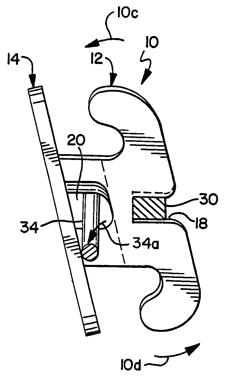
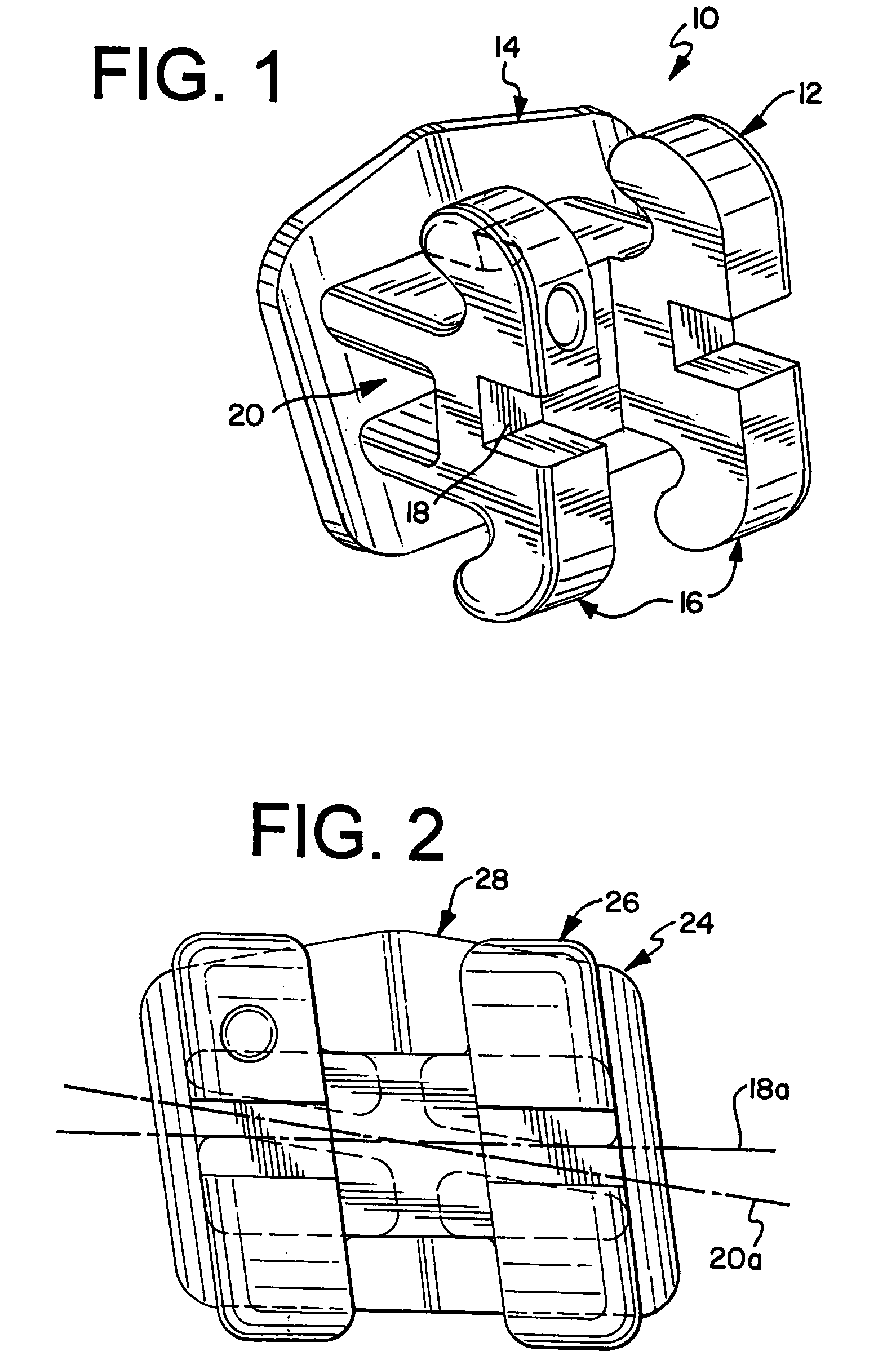
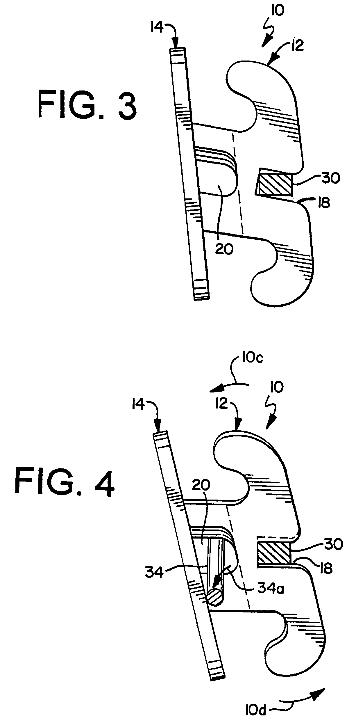
[0064]The improved edgewise bracket of the present invention solves the problem of capturing lost torque created in edgewise brackets during the final stages of orthodontic treatment due to the inevitable vertical tolerances necessary between the archwire slots and archwires themselves necessitated to permit the insertion of the wires. The invention avoids the heretofore often used wire-bending techniques to capture the lost torque by providing tunnels or lumens in the brackets angularly disposed to the archwire slot and which receive a small flexible wire for applying forces to the brackets to cause the diagonally opposed ends of the archwire slots to engage the upper and lower surfaces of a rectangular archwire to attain the predetermined torque value of the bracket.

[0065]The invention includes the use of tunnels or lumens for receiving small flexible wires to be activated while in the presence of the rectangular archwire which is retained in the rectangular archwire slots of the ...


PUM


Abstract

An edgewise orthodontic bracket for use in an edgewise or straight-wire technique having a standard horizontally opening rectangular archwire slot and a mesiodistally extending tunnel or lumen separate from and vertically angled to the archwire slot for receiving a relatively small flexible wire during the use of an undersize rectangular archwire in the archwire slot to apply a force to the bracket for capturing lost torque.

Description

[0001]This invention relates in general to an edgewise orthodontic bracket having a rectangular archwire slot for receiving a rectangular archwire and a tunnel for receiving a small flexible wire to apply forces to the bracket and eliminate the play or tolerance between a vertically undersize archwire and the archwire slot, and more particularly to a new and improved orthodontic edgewise bracket for capturing lost torque and achieving more accurate results in the final positioning of teeth.BACKGROUND OF THE INVENTION[0002]When Dr. Edward Angle first introduced the brackets and archwires for the edgewise mechanism in 1925, the archwires were made of gold and the brackets from a solid block of metal. Dr. Angle originally claimed his edgewise archwire was “ . . . exactly 0.022 inch in thickness and 0.028 inch in width, and it most accurately fits the slots in brackets.” (Angle, E. H., The latest and best in orthodontic mechanism. Dental Cosmos 1928;70:1143–1158.) Dr. Angle's use of the...

Claims


Application Information

Patent Timeline
IPC IPC(8): A61C7/12
CPCA61C7/12A61C7/14A61C7/143
Inventor KESLING, PETER C.PARKHOUSE, RICHARD C.KESLING, CHRISTOPHER K.
Owner IMPACT RES
Learn More