Transmitting method and transmitter apparatus
a transmitter and transmitter technology, applied in the field of transmitter methods and transmitter apparatuses, can solve the problems of affecting the performance of the transmission signal, and widening the spectrum of the transmitter apparatus, so as to achieve the effect of reducing the frequency of the transmitter and reducing the distortion
- Summary
- Abstract
- Description
- Claims
- Application Information
AI Technical Summary
Benefits of technology
Problems solved by technology
Method used
Image
Examples
exemplary embodiment 1
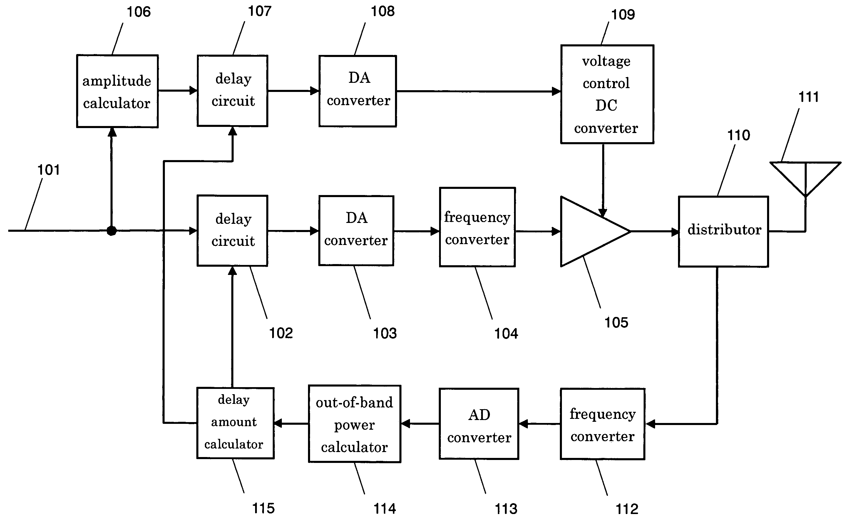
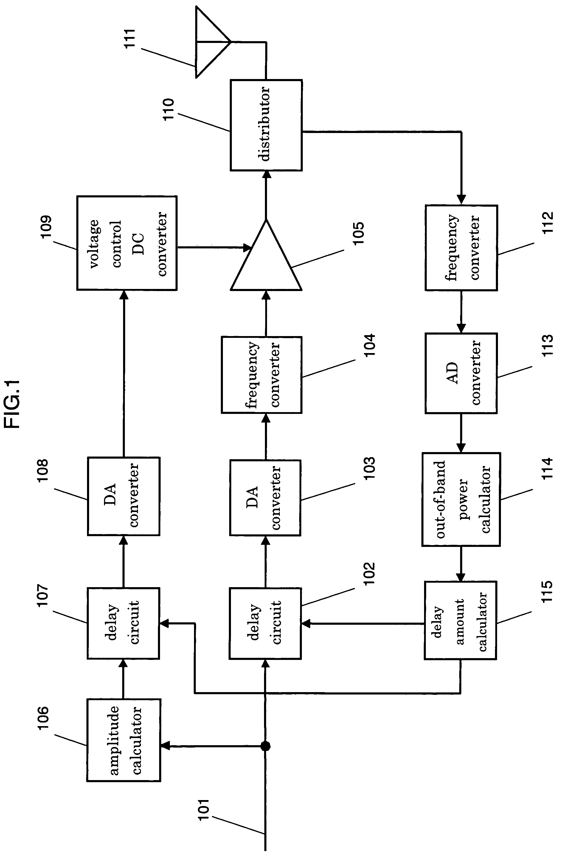
[0030]FIG. 1 shows a block diagram illustrating a transmitter apparatus in accordance with the first exemplary embodiment of the present invention. Delay circuit 102 delays its input signal before outputting it. DA converter 103 converts its input signal into an analog signal. Frequency converter 104 up-converts its input signal into an RF signal. Power amplifier 105 amplifies its input signal. Amplitude calculator 106 calculates an amplitude component of its input signal before outputting it.
[0031]Delay circuit 107 delays its input signal. DA converter 108 converts its input signal into an analog signal. Voltage control DC converter 109 outputs a voltage that controls power amplifier 105 based on an output from DA converter 108. Distributor 110 distributes an output from power amplifier 105 to antenna 111 and frequency converter 112.
[0032]Antenna 111 transmits the signal distributed by distributor 110. Frequency converter 112 converts a frequency of the signal distributed by distri...
exemplary embodiment 2
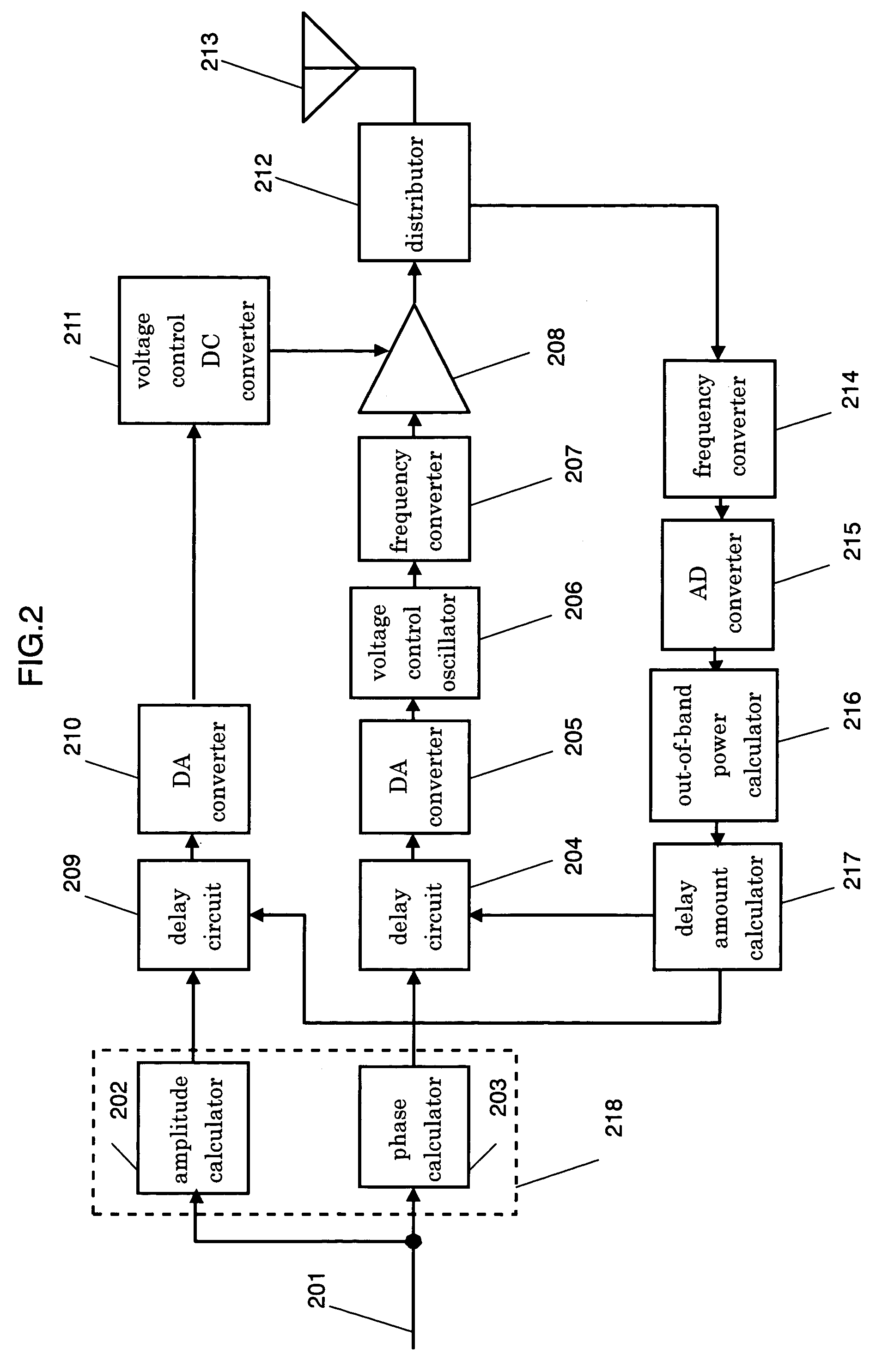
[0041]FIG. 2 shows a block diagram illustrating a transmitter apparatus in accordance with the second exemplary embodiment of the present invention. Computation circuit 218 is formed of amplitude calculator 202 and phase calculator 203. Amplitude calculator 202 calculates an amplitude component of transmission base-band signal 201 supplied thereto. Phase calculator 203 calculates a phase component of signal 201 supplied thereto. Delay circuit 204 delays an output signal supplied from phase calculator 203.
[0042]DA converter 205 converts the output from delay circuit 204 into an analog signal. Voltage control oscillator 206 carries out phase modulation based on the output from DA converter 205. Frequency converter 207 converts a frequency of the output from oscillator 206. Power amplifier 208 amplifies the output from frequency converter 207 up to a desirable level. Delay circuit 209 delays the output supplied from amplitude calculator 202.
[0043]DA converter 210 converts the output si...
exemplary embodiment 3
[0052]FIG. 3 shows a block diagram illustrating a transmitter apparatus in accordance with the third exemplary embodiment of the present invention. Computation circuit 518 is formed of amplitude calculator 502 and phase calculator 503. Amplitude calculator 502 calculates an amplitude component of transmission base-band signal 501 supplied thereto. Phase calculator 503 calculates a phase component of signal 501 supplied thereto. Delay circuit 504 delays an output signal supplied from phase calculator 503.
[0053]DA converter 505 converts the output from delay circuit 504 into an analog signal. Voltage control oscillator 506 carries out phase modulation based on the output from DA converter 505. Frequency converter 507 converts a frequency of the output from oscillator 506. Power amplifier 508 amplifies the output from frequency converter 507 up to a desirable level. Delay circuit 509 delays the output supplied from amplitude calculator 502.
[0054]DA converter 510 converts the output sig...
PUM
 Abstract
Description
Claims
Application Information
 - R&D
- Intellectual Property
- Life Sciences
- Materials
- Tech Scout
- Unparalleled Data Quality
- Higher Quality Content
- 60% Fewer Hallucinations
Browse by: Latest US Patents, China's latest patents, Technical Efficacy Thesaurus, Application Domain, Technology Topic, Popular Technical Reports.
© 2025 PatSnap. All rights reserved.Legal|Privacy policy|Modern Slavery Act Transparency Statement|Sitemap|About US| Contact US: help@patsnap.com


