
Methods of making balloon catheter tip

a balloon catheter and tip technology, applied in the field of medical devices, can solve the problems of less strong of a joint than is desirable, and less flexible butt seal itsel

Active Publication Date: 2007-08-28
CARDINAL HEALTH SWITZERLAND 515 GMBH
View PDF19 Cites 9 Cited by
  • Summary
  • Abstract
  • Description
  • Claims
  • Application Information

AI Technical Summary

Benefits of technology

[0005]During angioplasty, an expansive force may be applied to the lumen of the stenosis, which may be a vessel constriction or narrowing due to plaque buildup or thrombus, etc. This outward pressing of a narrowing at the desired site in a body passage is intended to partially or completely reopen or dilate that body passageway or lumen, increasing its inner diameter or cross-sectional area. The objective of this procedure is to increase the inner diameter or cross-sectional area of the vessel passage or lumen through which blood flows, to encourage greater blood flow through the newly expanded vessel.
[0036]The resulting tip provides a heat seal that is strong and flexible, and provides transitions in size and flexibility that may be tailored for desired characteristics.

Problems solved by technology

Such a stenosis may cause heart attack or stroke, which are significant health problems affecting millions of people each year.
However, a butt seal may present a sharp transition in material characteristics, such as lubricity or flexibility.
Also, a butt seal may itself be less flexible than is desirable, or may be less strong of a joint than is desirable.

Method used


Image

  • Methods of making balloon catheter tip
  • Methods of making balloon catheter tip
  • Methods of making balloon catheter tip

Examples


Embodiment Construction

[0023]The following description of the preferred embodiments of the present invention is merely illustrative in nature, and as such it does not limit in any way the present invention, its application, or uses. Numerous modifications may be made by those skilled in the art without departing from the true spirit and scope of the invention.

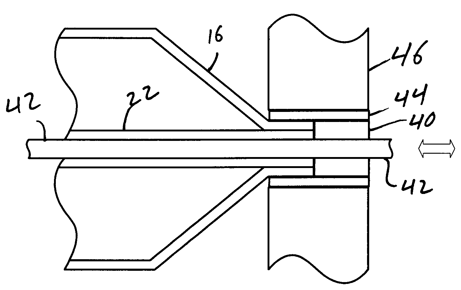
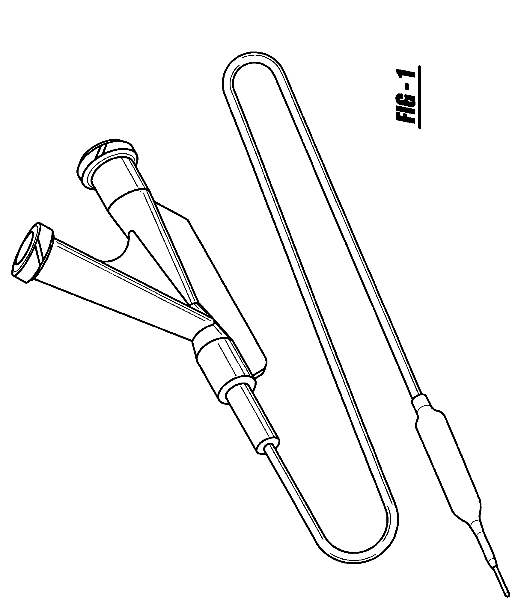
[0024]Referring to the drawings, balloon catheters and methods of making them are depicted, with one of the examples of a balloon catheter being shown generally at 10. The illustrated balloon catheter of course depicts only one of many different balloon catheter designs within the scope of the present invention.

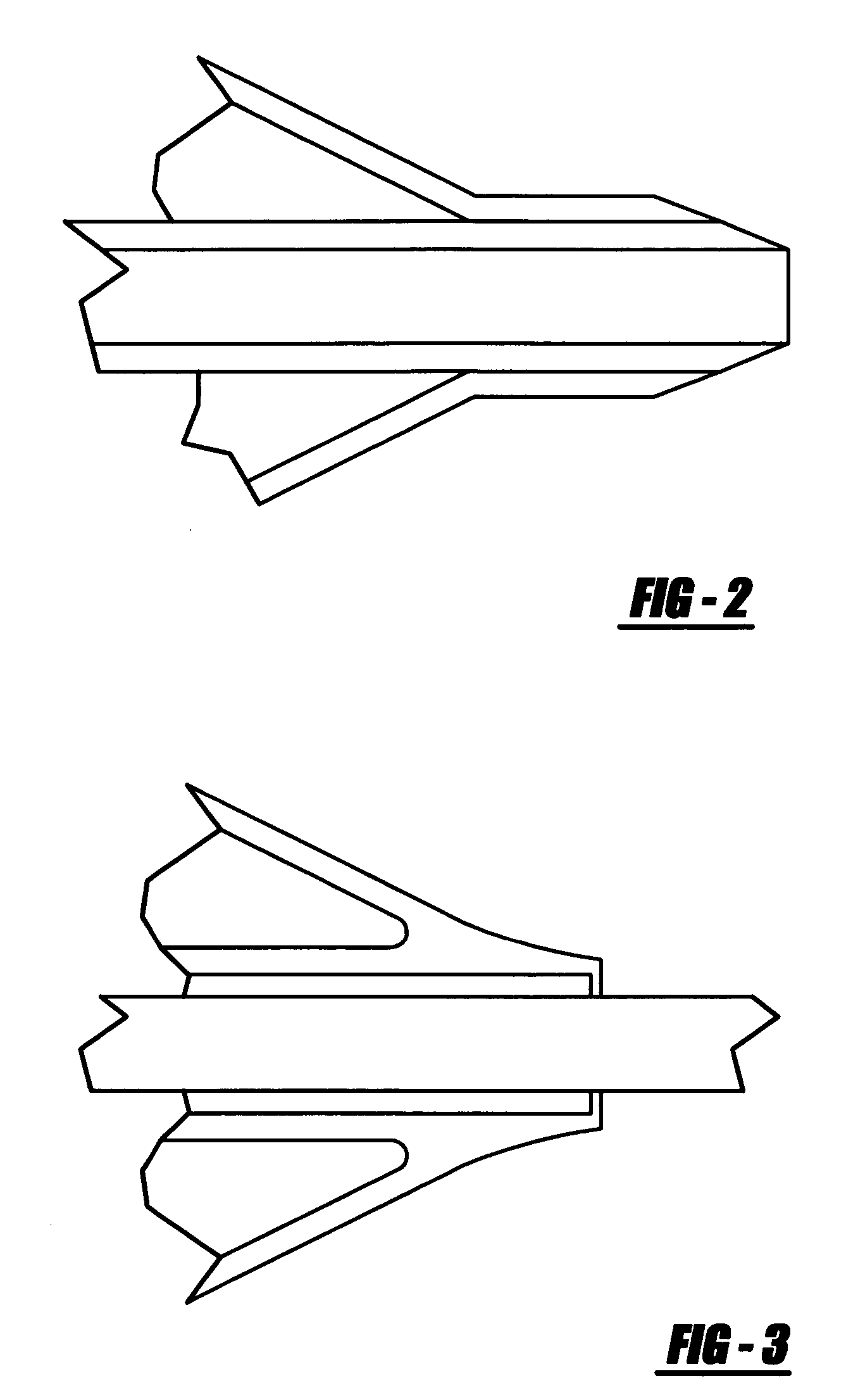
[0025]The drawings show an improved tip design and methods of the present invention, and includes a proximal hub 12, a flexible catheter shaft 14, and a balloon 16. The proximal hub 12 may provide an operating handle for a physician, as well as define a proximal guidewire port 18 and an inflation port 20.

[0026]At least a distal portion of the ...


PUM

PropertyMeasurementUnit
flexibleaaaaaaaaaa
compressive forceaaaaaaaaaa
temperatureaaaaaaaaaa

Abstract

A balloon catheter for medical treatment of a patient has an improved tip design and methods of making the tip. The balloon catheter has a flexible shaft with proximal and distal ends, a hub affixed to the proximal end, and a balloon affixed to the shaft near the distal end. At least a distal portion of the shaft includes a tubular inner body, and the balloon has a distal leg affixed to the inner body. A short, tubular tip member is placed in contact with the distal end of the inner body, and a shrink tube is placed around the point of contact. A wire mandrel is passed through a lumen defined by the inner body and tip member. While the shrink tube is heated, compressing the tip member and inner body, the mandrel is moved. This combination of heat, radial pressure, and mandrel movement causes a blending of the materials of the inner body and the tip member. The resulting joint of the tip member and inner body is both strong and flexible.

Description

BACKGROUND AND SUMMARY OF THE INVENTION[0001]1. Technical Background[0002]The present invention relates generally to medical devices, and more particularly to balloon catheter tip designs, and methods of making such catheter tips.[0003]2. Discussion[0004]Balloon catheters are used in a variety of therapeutic applications, including many vascular treatments such as angioplasty, and delivery of medical devices such as stents. Angioplasty can be used to treat vascular disease, in which blood vessels may be partially or totally blocked or narrowed by a lesion or stenosis. In many instances of vascular disease, a local area of a blood vessel may become narrowed. This narrowing is called a lesion or stenosis, and may take to form of hard plaque, cholesterol, fats, or viscous thrombus. Such a stenosis may cause heart attack or stroke, which are significant health problems affecting millions of people each year.[0005]During angioplasty, an expansive force may be applied to the lumen of the ...

Claims


Application Information

Patent Timeline
Patent Type & Authority Patents(United States)
IPC IPC(8): B29C61/02B29C65/18A61M25/00
CPCA61M25/001A61M25/1027
Inventor VAN OCKENBURG, BENSCHULTING, EDWIN A.SNIPPE, FREDERIK A.
Owner CARDINAL HEALTH SWITZERLAND 515 GMBH
Learn More