Reaction lever for a parking brake

a technology of a brake and a reaction lever, which is applied in the direction of brakes, actuators, drum brakes, etc., can solve the problems of excessive manual input force used to set the brake, damage to the brake components,

Inactive Publication Date: 2007-08-28
ROBERT BOSCH CORP
View PDF22 Cites 2 Cited by
  • Summary
  • Abstract
  • Description
  • Claims
  • Application Information

AI Technical Summary

Benefits of technology

[0004]In more particular detail, the brake assembly includes a first and second brake shoes that are retained on a backing plate wherein each of the first and second brake shoes is defined by having a first end and a second end with the first ends aligned with an actuator assembly and the second ends aligned with a spacer. The first and second brake shoes are urged toward the actuator assembly and spacer by a spring arrangement to establish a running clearance between a first friction pad of the first brake shoe and a second friction pad of the second brake shoe with the drum. An input force is applied through the actuator assembly to move the first ends and correspondingly the first and second friction pads into engagement with the drum to effect a brake application. The movement of the first ends of the first and second brake shoes results from an input force applied to a cable pulling on a lever in the actuator assembly to transmit an actuation force to the first ends of the first and second brake shoes. The lever is characterized by a substantially rectangular flat member having a first end and a second end. The first end has a cam surface that is aligned with the first ends of the first and second brake shoes by a pin while a tine is fixed to the second end and the cable attached to the end of the tines. Initially the tine is resiliently deflected with respect to the lever by a predetermined force from an attached position to a rest position and held in the rest position by a tab that engages the lever. With the tine retained in this rest position, the tine and second end of the lever move together in response to the pull of an input force to effect a brake application. When the input force exceeds the predetermined force, the additional input force pulls on and further deflects the tine such that the tine and cable continue to move at a same rate while the movement of the second end is reduced as a function of the further deflection and as a result the actuation force supplied to the first end of the lever for moving the first ends of the first and second brake shoes is correspondingly reduced.
[0005]An advantage of the lever of the present invention for use in a parking brake structure of a brake assembly is results in limiting an actuation force that may be applied to move first and second brake pad into engagement with a drum to effect a brake application.
[0006]A further distinction of the lever of the invention resided in an ability of a input force being applied in a linear manner to effect a brake application until a predetermined input force is reached and thereafter an increase in an input force is proportionally reduced as a function of the elasticity of a tine through which the input force is transmitted to a lever for moving first and second brake shoes into engagement with a drum.
[0007]According to this invention, a parking brake assembly includes a lever having a leaf that extends there from for transmitting an input force from a cable to provide an actuation force for moving of brake shoes into engagement with a drum to effect a brake application wherein the resiliency of the leaf determines the limits of an actuation force that is derived from an input force.

Problems solved by technology

However, under some circumstances such as moving a vehicle without the release of the parking brake it is possible that a manual input force used to set the parking brake may be excessive and as a result the components of a brake may be damaged.

Method used


Image

  • Reaction lever for a parking brake
  • Reaction lever for a parking brake
  • Reaction lever for a parking brake

Examples


Embodiment Construction

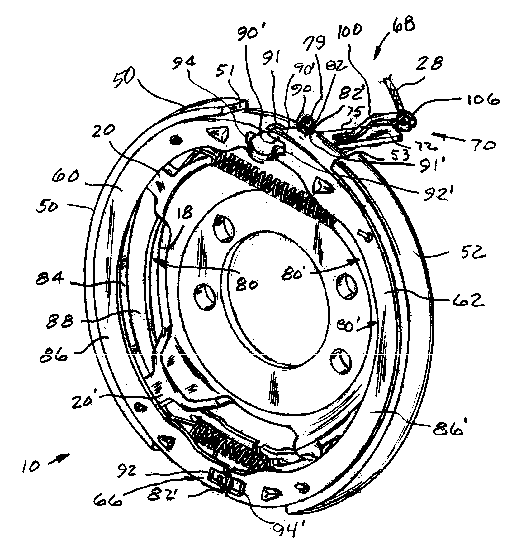
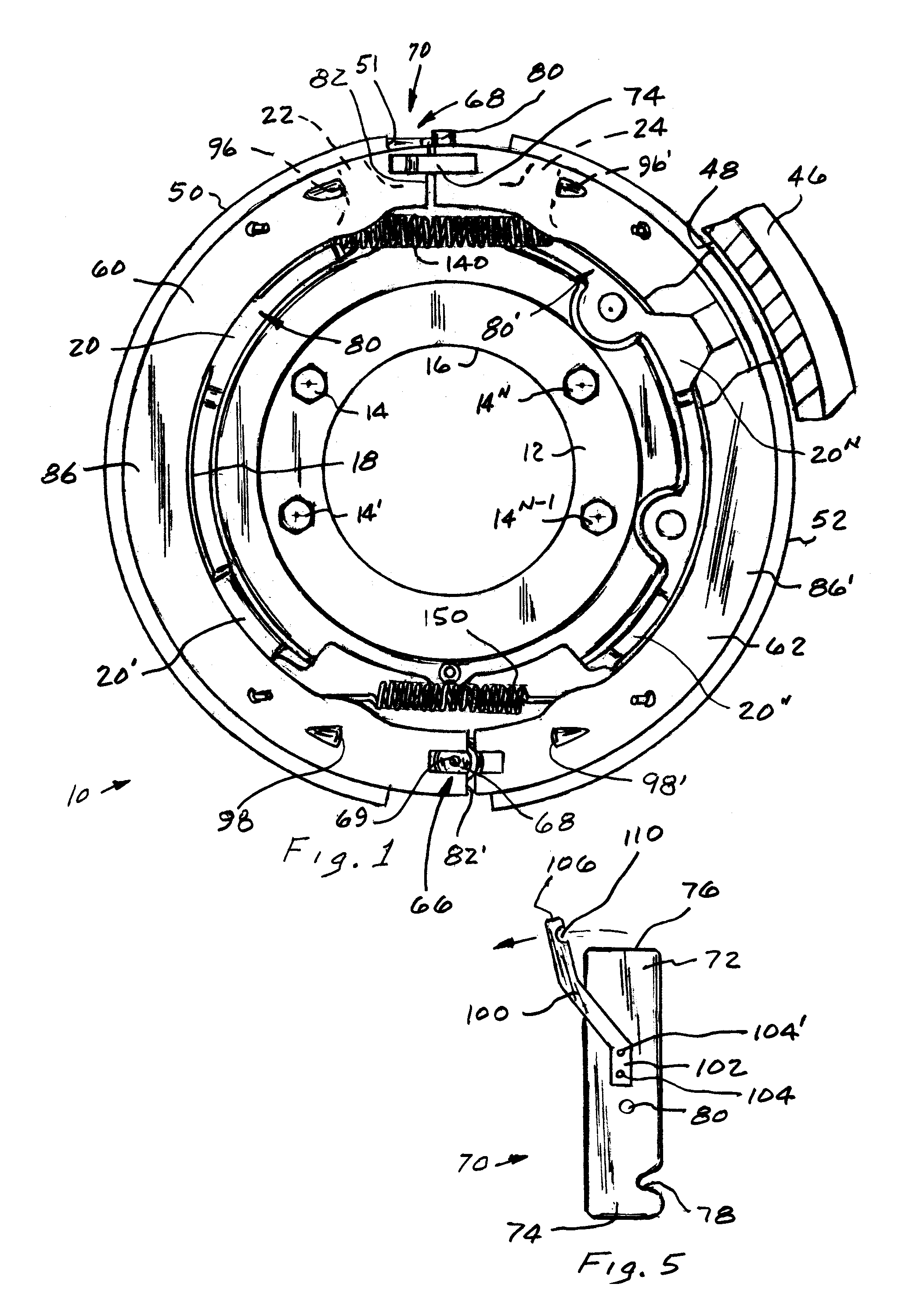
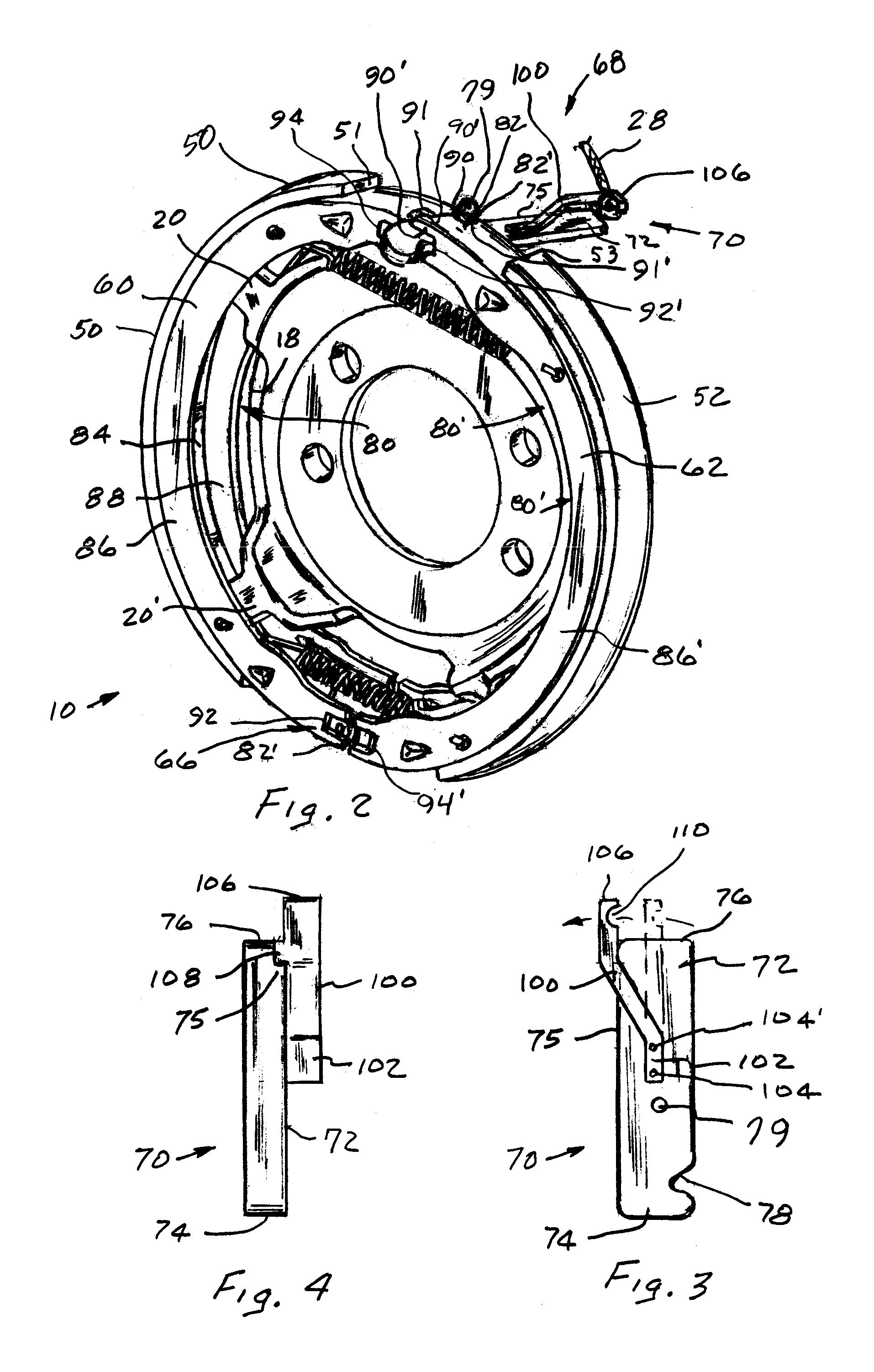
[0013]The brake 10, shown in FIGS. 1 and 2, is part of a brake system the functions as a service brake and a parking brake for a vehicle. The parking brake is often referred to as a drum-in-hat and includes a drum 46 that is rotatable about an axis of an axle shaft that has an inner cylindrical surface 48 to define a braking surface for first 50 and second 52 friction surfaces on first 60 and second 62 brake shoes that are manually moved by an actuation arrangement 68, of the present invention, from a position of rest to effect a desired parking brake application.

[0014]In more detail, the brake 10 as shown in FIGS. 1 and 2, includes a disc 12 that is fixed by bolts 14, 14′ . . . 14n to a vehicle. The disc 12 has an opening 16 therein through which the axle shaft passes and a peripheral surface 18 with a plurality of radial guides 20,20′ . . . 20n interspersed between a first radial abutment 22 and a second radial abutment 24 in a manner as illustrated in U.S. Pat. No. 6,729,449. Eac...


PUM


Abstract

A lever for moving first and second brake shoes into engagement with a drum to effect a brake application. The lever has a first end connected to the brake shoes and a second end with a tine fixed thereto to which a cable is connected to apply an input force to effect a brake application. A predetermined force is applied to the tine to deflect the tine and a tab engages the lever to hold the tine in the deflected position. The tine and second end of the lever move in unison in response to an input force until the input force exceeds the predetermined force such that while the tine and cable continue to move in unison the deflection of the tine proportionally reduces the movement of the first end of the lever and as a result an actuation force applied to effect a brake application is correspondingly reduced.

Description

[0001]This invention relates to a lever through which an input force is applied to move first and second friction pads associated with first and second brake shoes into engagement with a drum to effect a brake application is limited.BACKGROUND OF THE INVENTION[0002]Disc brakes such as disclosed in U.S. Pat. Nos. 5,180,037 and 5,529,149, have been utilized on rear axles brake systems of vehicles as both a service braking and a parking brake. In such disc brake the service brake is a hydraulically actuated while the parking brake is typically actuated by a lever arrangement. Various lever arrangements have been used to actuate such as a cam mechanism as disclosed in U.S. Pat. No. 5,360,086, a scissors type mechanism as disclosed in U.S. Pat. No. 6,729,449 or a lever as disclosed in U.S. Pat. No. 6,206,148 to supply an input force that moves brake shoes into engagement with a drum to effect a brake application. However, under some circumstances such as moving a vehicle without the rele...

Claims


Application Information

Patent Timeline
Patent Type & Authority Patents(United States)
IPC IPC(8): F16D51/00
CPCF16D51/00F16D2125/64
Inventor MACKIEWICZ, JOHN EDMUND
Owner ROBERT BOSCH CORP
Why Eureka
Try Eureka