Method for controlling power level of received signal in ultra wide band transmission system

a transmission system and power level technology, applied in the direction of power management, wireless communication, gain control, etc., can solve problems such as complex transmission systems

Inactive Publication Date: 2007-08-21
ELECTRONICS & TELECOMM RES INST
View PDF13 Cites 2 Cited by
  • Summary
  • Abstract
  • Description
  • Claims
  • Application Information

AI Technical Summary

Benefits of technology

[0012]It is, therefore, an object of the present invention to provide a method for controlling the power level of a received signal in a ultra wide-band (UWB) transmission system.

Problems solved by technology

However, the one major drawback of compensating the signal power loss in the conventional transmission system is in that a VGA should be designed to have the dynamic range on the order of the tens dB.
Another drawback of compensating the signal power loss in the conventional transmission system is in that a VGA should be designed for each frequency band.
In this case, the transmission system is complex.

Method used


Image

  • Method for controlling power level of received signal in ultra wide band transmission system
  • Method for controlling power level of received signal in ultra wide band transmission system
  • Method for controlling power level of received signal in ultra wide band transmission system

Examples


Embodiment Construction

[0025]Other objects and aspects of the invention will become apparent from the following description of the embodiments with reference to the accompanying drawings, which is set forth hereinafter.

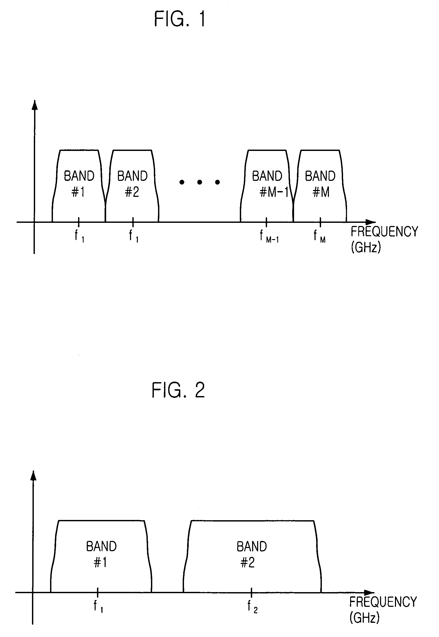
[0026]FIG. 2 is a graph showing frequency bands for use in a 2-band transmission system. In the 2-band transmission system wherein the minimum and maximum frequency bands are in use, the power level of one received signal is at least twice as big as that of the other received signal. The 2-band transmission system includes all such transmission systems using more than one frequency band.

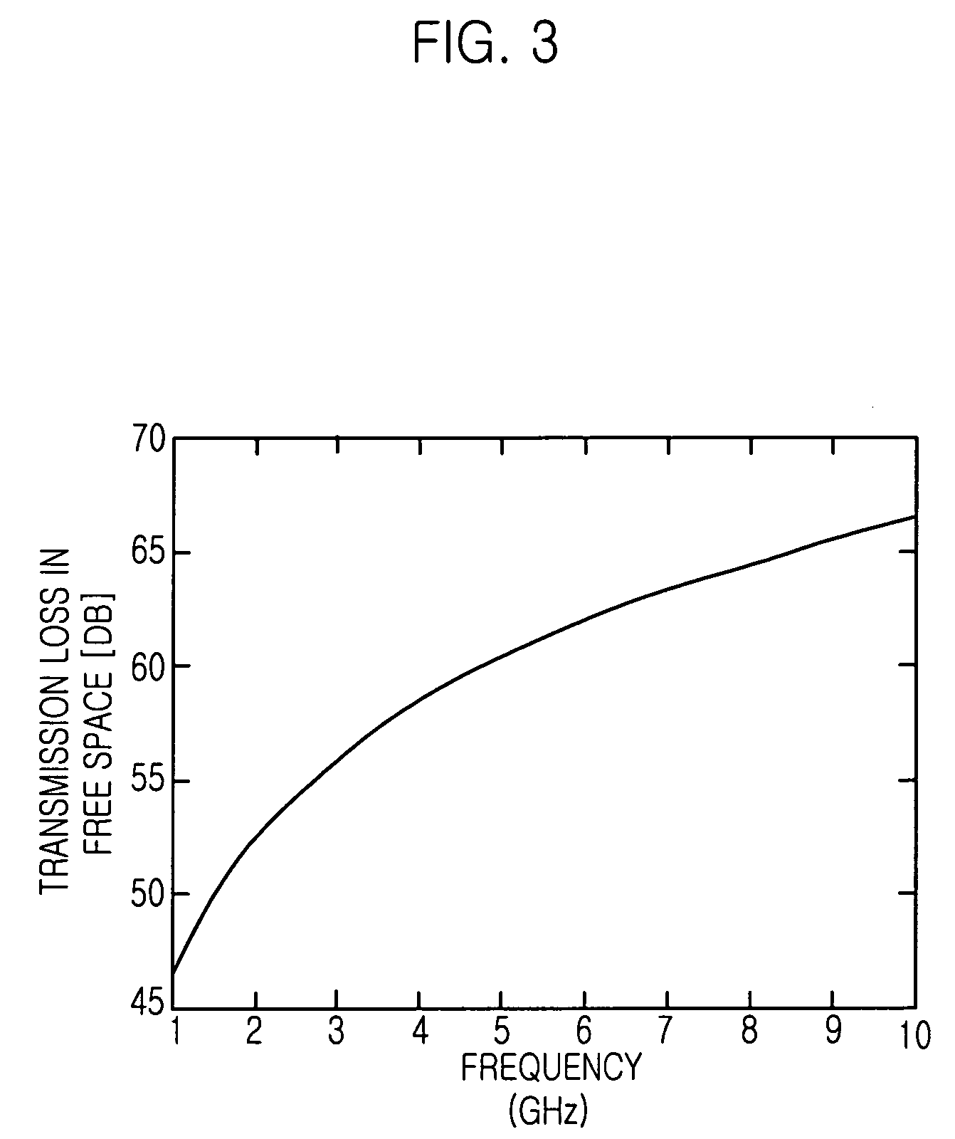
[0027]FIG. 3 is a graph describing the free space loss (FSL) of transmission signal which can be obtained by Eq. (1).

[0028]As shown, each point on the horizontal axis represents frequency measured in GHz and each point on the vertical axis represents the amount of the FSL measured in dB.

[0029]FIG. 4A is a graph describing the signal attenuation in the FSL on each frequency band in a conventional transmission...


PUM


Abstract

Disclosed is a method for controlling power level of received signal in an ultra wide band transmission system which uses multi frequency bands, and includes a pre-gain controller (PGC) and a voltage gain amplifier (VGA). The method for controlling a power level of a received signal includes the steps of: a) at the PGCs, detecting which multi frequency band is used in a transmitter of the transmission system; b) at the PGCs, obtaining the voltage gain owing to the discrepancy in the power levels of the received signals; and c) at the PGCs, compensating for the power loss based on the voltage gain.

Description

FIELD OF THE INVENTION [0001]The present invention relates to a method for controlling a power level of a received signal in a ultra wide-band (UWB) transmission system and a computer-readable recording medium for recording a program that implements the same method; and, more particularly, to a method for restoring a power level of a received signal to compensate for the signal power loss in an ultra wide-band (UWB) transmission system in which multi frequency bands are in use, and a computer-readable recording medium for recording a program that implements the same method.DESCRIPTION OF RELATED ART [0002]In general, when a radio wave signal is transmitted from one point (source) to another point (target) in a free space, power levels of the received radio wave signals are different depending on the distance between the two points. In the free space, the electric field intensity (E) of the radio wave signal, which is radiated by an isotropic antenna as a transmission power Pt [Watts...

Claims


Application Information

Patent Timeline
Patent Type & Authority Patents(United States)
IPC IPC(8): H04B1/06H04B7/26H03G3/30H04B1/69H04B7/005
CPCH03G3/3052H04B1/71637H04W52/52H03G2201/103H03G2201/502H03G2201/702H04W52/36
Inventor LEE, HYUNG-SOOCHO, SANG-INKANG, KYU-MINKIM, CHANG-JOO
Owner ELECTRONICS & TELECOMM RES INST
Why Eureka
Try Eureka