Electronic disabling device having adjustable output pulse power

a technology of electronic disabling device and output pulse power, which is applied in the direction of electrical equipment, instruments, weapons, etc., can solve the problems of difficulty for muscle cells to decipher original signals, and achieve the effect of power control level

Active Publication Date: 2008-12-04
DEFENSE TECH INC
View PDF4 Cites 2 Cited by
  • Summary
  • Abstract
  • Description
  • Claims
  • Application Information

AI Technical Summary

Benefits of technology

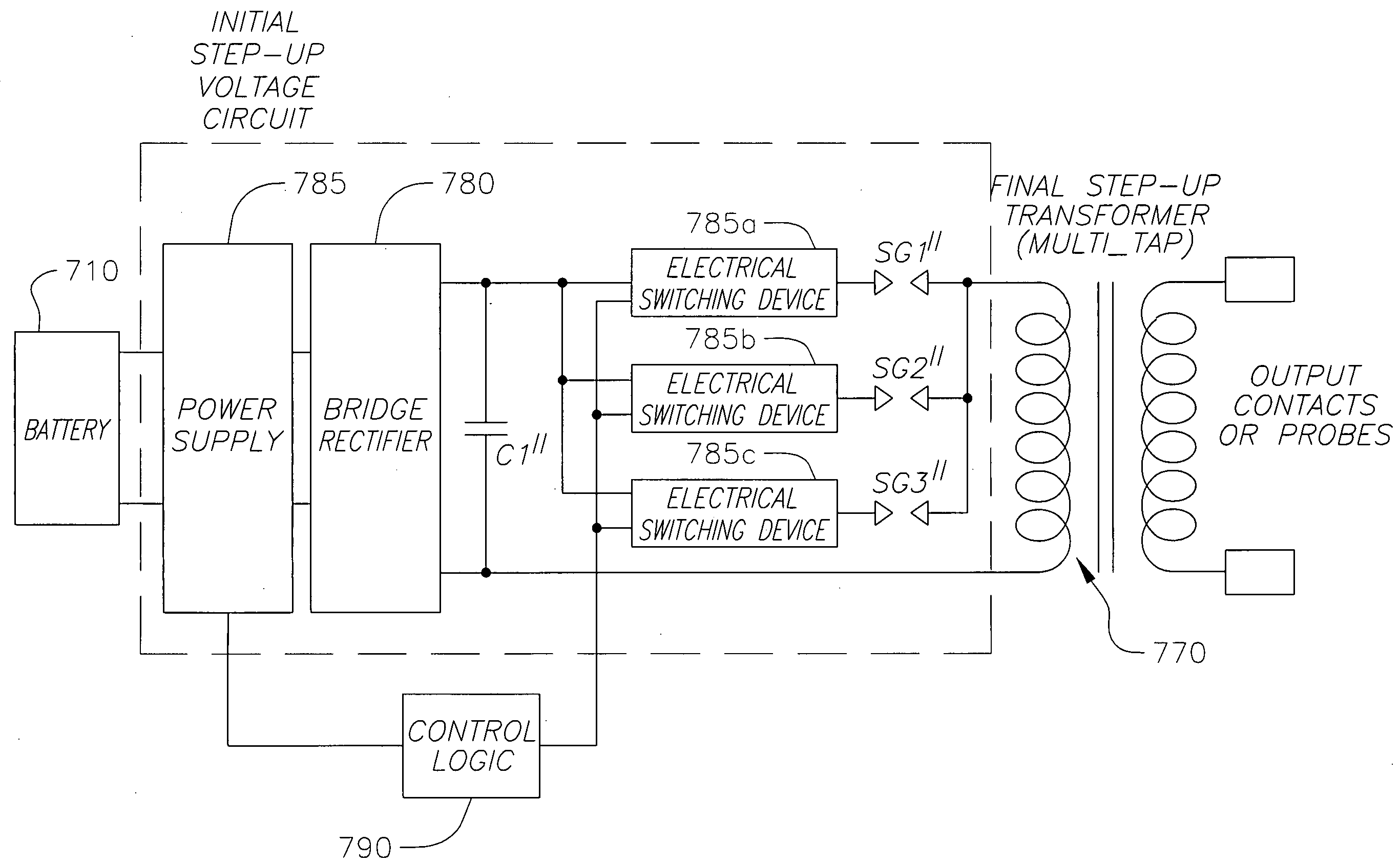
[0008]The present invention relates to a system and / or an associated method for providing an electronic disabling device with a level of power control. The invention provides the electronic disabling device with multiple selectable power levels in one device package. This would allow a user of the electronic disabling device to start with a low power setting (e.g., the lowest power setting) and if the power was not effective, incrementally increase the power until it was effective. This adds a level of safety such that the user does not apply a power level to a live target that might possibly be unsafe to that particular individual.

Problems solved by technology

The brain's original signals are mixed in with random noise, making it very difficult for the muscle cells to decipher the original signals.

Method used


Image

  • Electronic disabling device having adjustable output pulse power
  • Electronic disabling device having adjustable output pulse power
  • Electronic disabling device having adjustable output pulse power

Examples


Embodiment Construction

[0024]In the following detailed description, only certain exemplary embodiments of the present invention are shown and described, by way of illustration. As those skilled in the art would recognize, the described exemplary embodiments may be modified in various ways, all without departing from the spirit or scope of the present invention. Accordingly, the drawings and description are to be regarded as illustrative in nature, and not restrictive.

[0025]There may be parts shown in the drawings, or parts not shown in the drawings, that are not discussed in the specification as they are not essential to a complete understanding of the invention. Like reference numerals designate like elements.

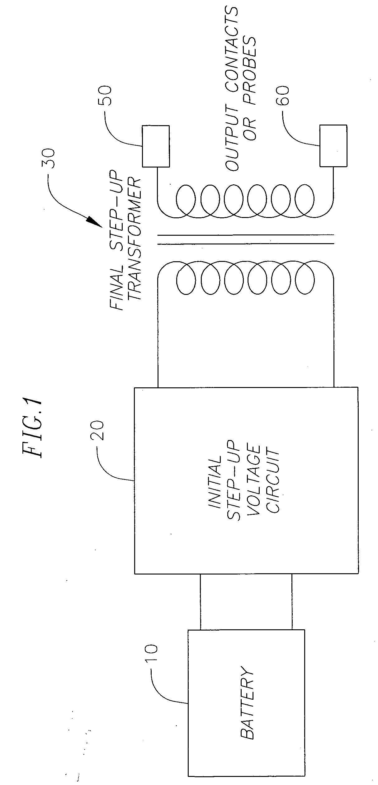
[0026]Referring to FIG. 1, an example of an electronic disabling device is shown to include a battery 10, an initial step-up voltage circuit 20, a trigger (not shown), a final step-up transformer 30, a first electrically conductive output contact (or probe) 50, and a second electrically conductive o...


PUM


Abstract

An electronic disabling device with multiple adjustable power levels and a method of providing the same. The electronic disabling device includes an initial step-up voltage circuit coupled to receive an initial power from a battery and a final step-up transformer (e.g., a plain transformer, an autoformer, etc.) adapted to provide an output power. In addition, a power control circuit is coupled between the initial step-up voltage circuit and the final step-up transformer to adjust the power levels of the output power provided by the final step-up transformer.

Description

CROSS-REFERENCE TO RELATED APPLICATIONS[0001]This application claims priority to and the benefit of U.S. Provisional Application No. 60 / 655,145, filed on Feb. 22, 2005, and U.S. Provisional Application No. 60 / 657,294, filed on Feb. 28, 2005, the entire contents of both of which are incorporated herein by reference.FIELD OF THE INVENTION[0002]The present invention relates generally to the field of an electronic disabling device for immobilizing a live target. More specifically, the present invention is related to an electronic disabling device having adjustable output pulse power and a method for providing the same.BACKGROUND OF THE INVENTION[0003]An electronic disabling device can be used to refer to an electrical discharge weapon or a stun gun. The electrical discharge weapon connects a shocking power to a live target by the use of darts projected with trailing wires from the electrical discharge weapon. The shocks debilitate violent suspects, so peace officers can more easily subd...

Claims


Application Information

Patent Timeline
Patent Type & Authority Applications(United States)
IPC IPC(8): H01T23/00
CPCF41H13/0025G05F1/12H05C1/06
Inventor RUTZ, COREYKRAMER, MICHAEL
Owner DEFENSE TECH INC
Why Eureka
Try Eureka