
Generator of a time-variable magnetic field and magnetic resonance device

a technology of magnetic field and generator, applied in the direction of magnetic measurement, measurement device, instruments, etc., can solve the problems of more compact structure, smaller size, and cost-effective structure, and achieve the effect of reducing h field, efficient generation of magnetic field, and reducing magnetic energy density

Inactive Publication Date: 2007-08-21
SIEMENS HEALTHCARE GMBH
View PDF28 Cites 0 Cited by
  • Summary
  • Abstract
  • Description
  • Claims
  • Application Information

AI Technical Summary

Benefits of technology

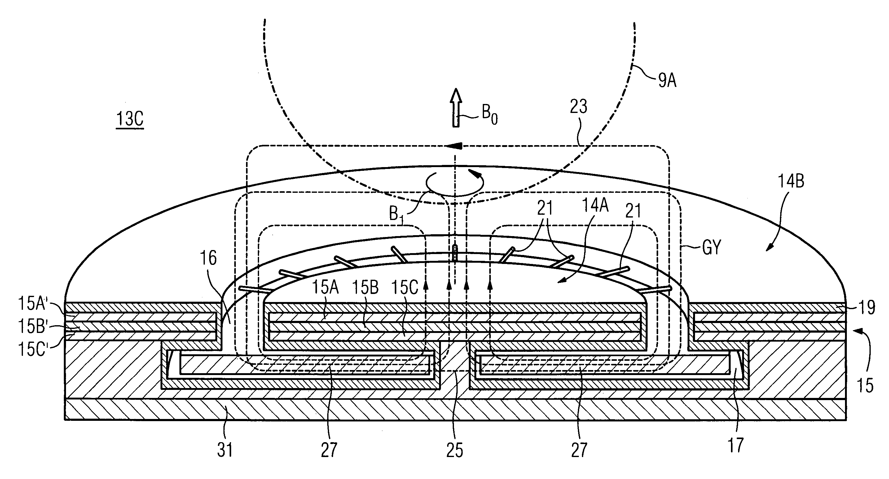
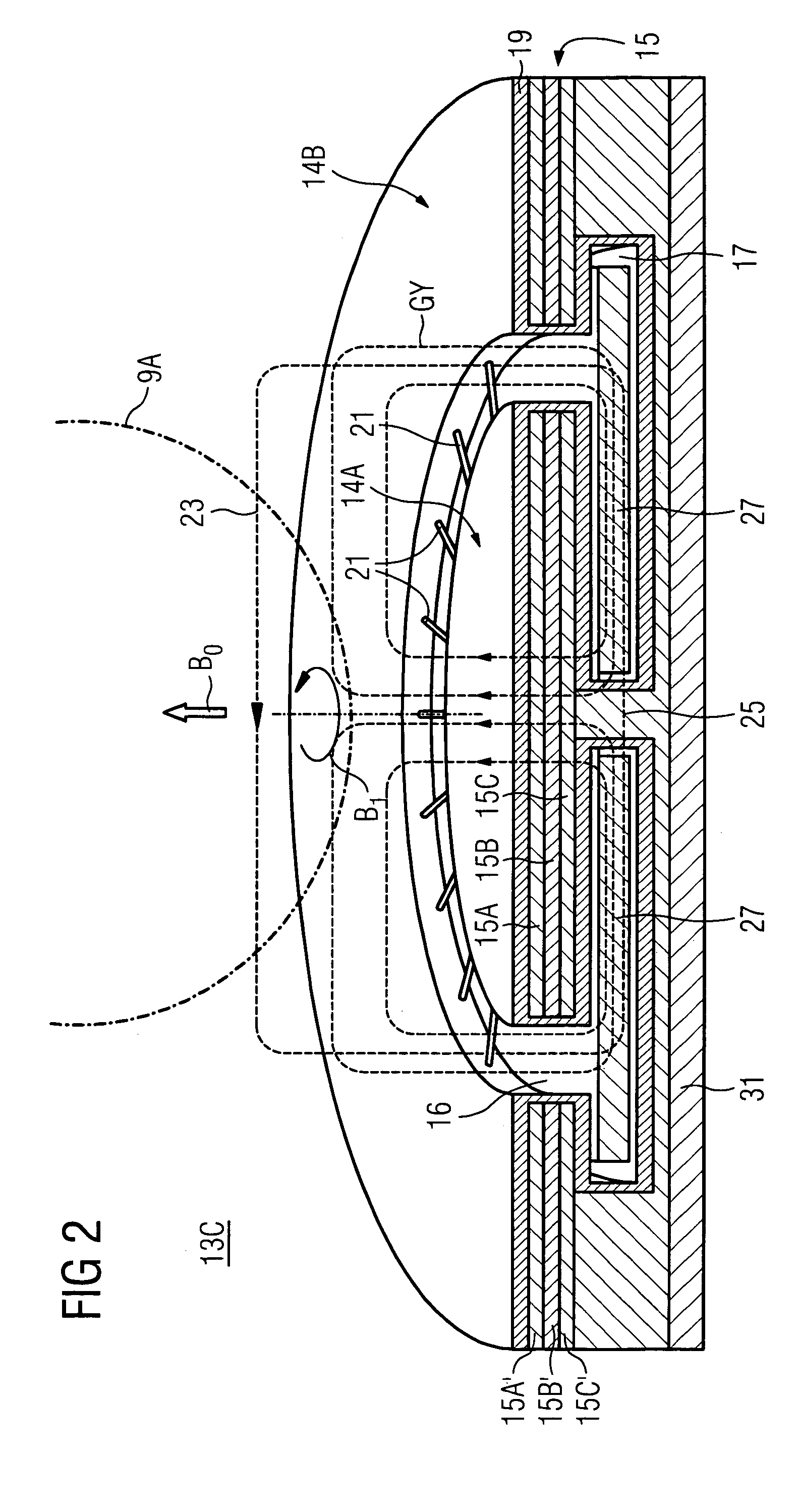
[0011]An advantage of the invention lies in the fact that the sub-assembly influences with the magnetizable material the magnetic field (H field) which is present in the field flux return space, the magnetic induction (B field) remaining the same. This enables efficient generation of a magnetic field (B field) in the examination space since, with the current from the generator being the same, a reduced H field and thus a lower magnetic energy density, proportional to H×B, is present in the field flux return space. Here, the H field is essentially inversely proportional to the effective permeability of the magnetizable material, effective permeability being understood to be the permeability which can be assigned to the entire field flux return space. Consequently, the same magnetic field can be generated in gradient conductors with less current, for example. Furthermore, a field flux return space can be realized that is smaller than it would be without a sub-assembly of this type, while the magnetic field strength in the examination space remains the same. This leads to smaller, more compact and thus more cost-effective structures.
[0012]A further advantage is based upon the fact that because of the magnetization a diminished ‘active’ magnetic field is present, i.e. reduced magnetic interaction takes place with electrical components which are arranged in the proximity of the field flux return space.
[0013]Because of the reduced H field, lower ohmic losses occur in adjacent electrical components, for example in electrical conductors, because of the time-variable magnetic field. Accordingly, the time-variable magnetic field can be generated more efficiently since less current has to flow in the gradient coil. For this reason also, a field flux return space can be realized that is smaller than it would be without a sub-assembly of this type, while the magnetic field strength in the examination space remains the same. This leads, as stated, to smaller, more compact and thus more cost-effective structures.
[0014]A great variety of types of time-variable magnetic fields is generated in a magnetic resonance device: For example, high-frequency fields are irradiated into the examination space with the aid of a high-frequency antenna unit having an antenna conductor for stimulating tissue located there to emit magnetic resonance signals. Furthermore, so-called gradient fields which produce a location-dependence of the emitted magnetic resonance signal are needed e.g. for location coding of the examination space. A primary gradient field of this type is generated with the aid of a primary gradient coil having a gradient conductor through which very strong currents flow. Often, to offset the primary gradient field outside the examination space, a secondary gradient-coil unit having a secondary gradient conductor is used, the secondary gradient-coil unit usually being further away from the examination space than the primary gradient-coil unit. The conductors mentioned are generally fashioned differently in accordance with their function and arranged in the magnetic resonance device.
[0015]One or more of these conductors can generate magnetic fields individually or jointly, generation with the aid of the sub-assembly being more efficient than without, so that, as stated, less current, for example, is needed and / or more space is available because of a smaller and more compact design. The magnetic fields in the field flux return space cause losses, for example through induced currents in the adjacent conductive HF shield. These are, since the magnetic energy density of the magnetic field in the field flux return space is generally greater than in the examination space, correspondingly large and their reduction with the aid of the sub-assembly has a direct impact on the efficiency of field generation.
[0016]In accordance with the invention, a sub-assembly which has magnetizable material is arranged in the field flux return space. Overall, this causes a reduction in magnetic energy density in the field flux return space and consequently for example reduced gradient currents and leads moreover to less disadvantageous effects of the magnetic field in the field flux return space on the adjacent electrical components.

Problems solved by technology

This leads to smaller, more compact and thus more cost-effective structures.

Method used


Image

  • Generator of a time-variable magnetic field and magnetic resonance device
  • Generator of a time-variable magnetic field and magnetic resonance device
  • Generator of a time-variable magnetic field and magnetic resonance device

Examples


Embodiment Construction

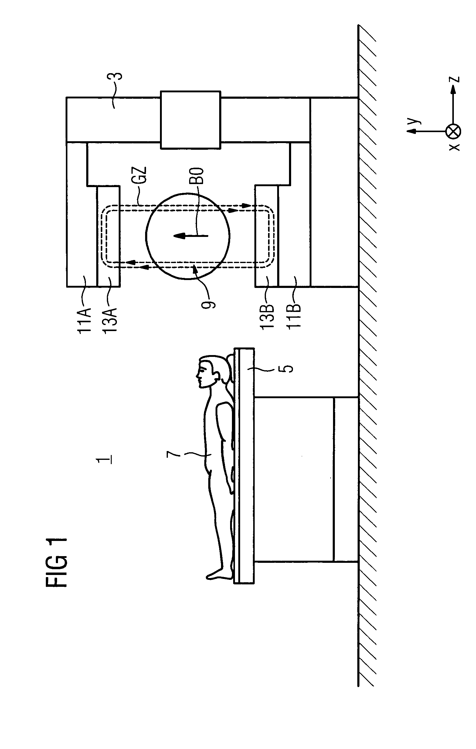
[0027]FIG. 1 shows schematically an open magnetic resonance device 1 for medically examining patients e.g. by means of MR tomography or MR spectroscopy in a main magnetic field B0 which is generated with a C-shaped main field magnet 3. The B0 field, which is constant over time, is generated according to the specified system of coordinates along the Y axis and lies e.g. in the order of 0.3 T. Also shown schematically is a patient bed 5 with which a patient 7 can be entered into the examination space 9. The examination space 9 is arranged in the air gap between two pole elements 11A,11B of the main field magnet 3.

[0028]The pole elements 11A,11B have e.g. solenoid actuators. Gradient-coil HF antenna units 13A,13B adapted to the pole elements 11A,11B generate in the examination space 9 on the one hand gradient fields GZ and on the other B1 high-frequency fields which are oriented perpendicularly to the main magnetic field B0. As an example, magnetic-field lines of a gradient field GZ ar...


PUM


Abstract

A generator (13A, . . . 13C) of a time-variable magnetic field (B1) of a magnetic resonance device (1) which has an examination space (9,9A) for accommodating at least one area to be examined of an examination subject (7), in which examination area the time-variable magnetic field (B1) is generated by means of a current through a conductor (15, 19, 31). The magnetic field lines (23) of the magnetic field (B1) close with the aid of a field flux return space (17), in which there is arranged at least one sub-assembly (27) which has magnetizable material. A reduction of a magnetic energy density in the field flux return space (17) is produced by this means. This increases e.g. the efficiency in the generation of high-frequency magnetic fields (B1) or of gradient fields with the aid of the conductor (15,19,31).

Description

CROSS REFERENCE TO RELATED APPLICATIONS[0001]This application claims priority to the German application No. 10 2004 003 535.0, filed Jan. 23, 2004 which is incorporated by reference herein in its entirety.FIELD OF INVENTION[0002]The invention relates to a generator of a time-variable magnetic field of a magnetic resonance device which has an examination space for accommodating at least one area of an examination subject, in which space the time-variable magnetic field is generated. The invention also relates to a magnetic resonance device having a generator of this type.BACKGROUND OF INVENTION[0003]Magnetic resonance technology is a known technology for, among other things, obtaining images of the inside of a body of an examination subject. In a magnetic resonance device (MR device), rapidly switched magnetic gradient fields which are generated by means of gradient coils are superimposed on a static main magnetic field B0 which is generated by a main field magnet. In order to emit m...

Claims


Application Information

Patent Timeline
Patent Type & Authority Patents(United States)
IPC IPC(8): G01V3/00G01R33/34G01R33/38G01R33/421G01R33/422
CPCG01R33/3806G01R33/34046G01R33/385G01R33/4215G01R33/422
Inventor HEID, OLIVERVESTER, MARKUS
Owner SIEMENS HEALTHCARE GMBH
Learn More