
Stent mounting assembly and a method of using the same to coat a stent

a technology of mounting device and stent, which is applied in the direction of prosthesis, blood vessels, packaging foodstuffs, etc., can solve the problems of removing some of the coating from the stent, affecting the stent, and causing other defects, so as to prevent the formation of the coating and minimize the amount or thickness of the coating

Inactive Publication Date: 2007-08-21
ABBOTT CARDIOVASCULAR
View PDF1008 Cites 61 Cited by
  • Summary
  • Abstract
  • Description
  • Claims
  • Application Information

AI Technical Summary

Benefits of technology

[0011]The present invention provides an apparatus for supporting a stent. The apparatus includes a mounting assembly for supporting a stent during a process of applying a coating substance to the stent. The mounting assembly prevents the formation of the coating or at least minimizes the amount or thickness of the coating that can be formed on the regions of the stent where the mounting assembly is in contact with the stent.
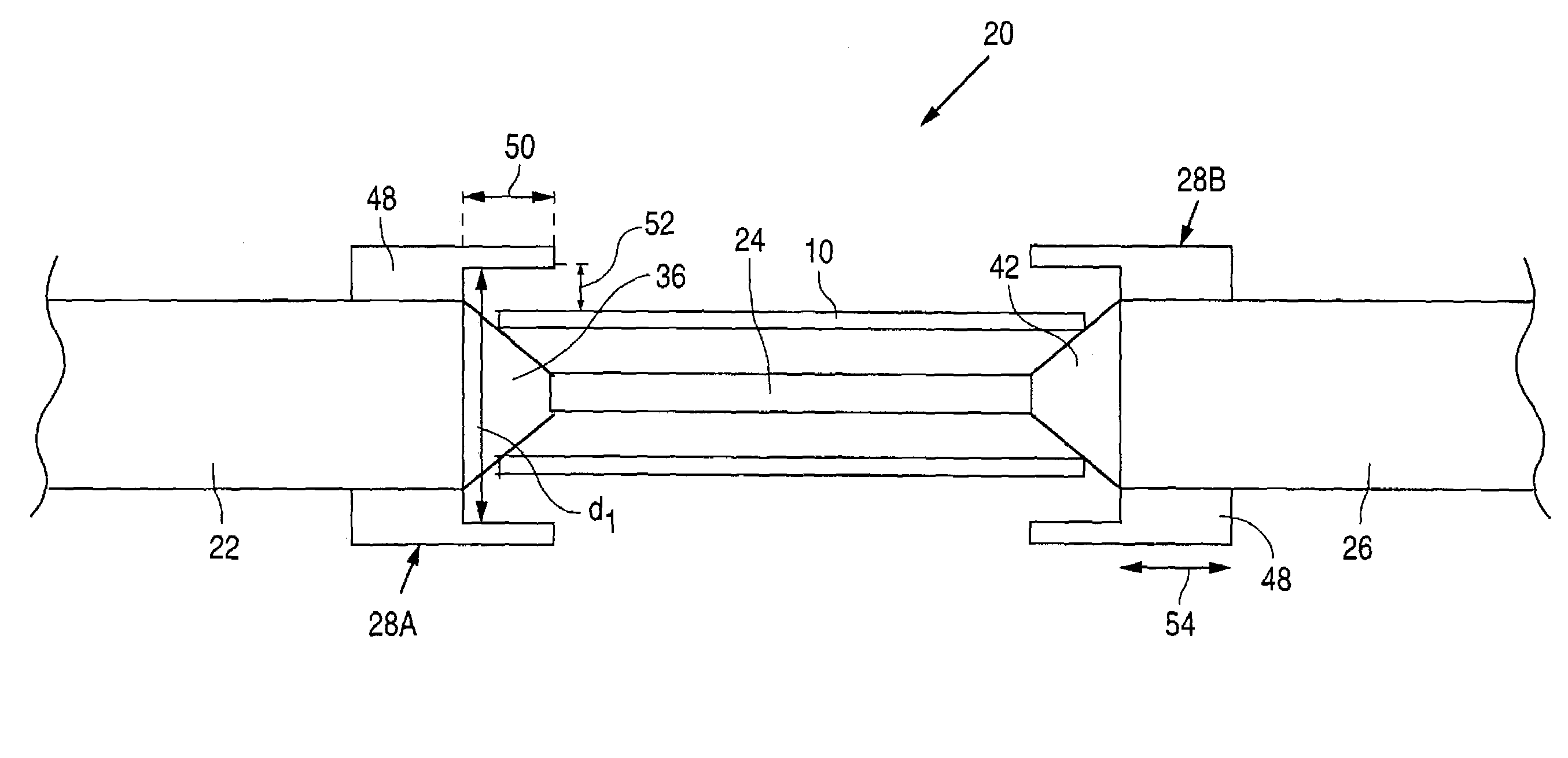
[0014]In yet another embodiment, the mounting assembly includes a first member having a first coning end that can be at least partially inserted within a first end of the stent and a second member having a second coning end that can be at least partially inserted within an opposing second end of the stent, the coning ends being in contact with the ends of the stent. In such an embodiment, the mounting assembly further includes a third member connecting the first member to the second member and shielding members supported by the first and second members for reducing or eliminating the amount of the coating substance that is applied to the first and second ends of the stent.
[0015]Also provided is an assembly for supporting a stent during the coating process. The assembly includes means for minimizing or eliminating the amount of coating material that can be applied to a designated area of the stent during the coating process. In one embodiment, the means is defined by a hollow body capable of surrounding a region of the stent without being in contact with the surface of the stent. In another embodiment, the amount of coating material can be minimized or eliminated at the regions where the stent is in contact with the assembly.
[0016]The present invention additionally provides a method of coating a stent. The method includes mounting a stent on a support assembly, wherein the support assembly is configured to reduce or eliminate the amount of coating that is applied to the regions where the stent is in contact with the support assembly. The method also includes applying a coating material to the stent for forming a coating.

Problems solved by technology

A shortcoming of the above-described method of medicating a stent is the potential for coating defects.
While some coating defects can be minimized by adjusting the coating parameters, other defects occur due to the nature of the interface between the stent and the apparatus on which the stent is supported during the coating process.
Upon the removal of the coated stent from the supporting apparatus, the excess coating may stick to the apparatus, thereby removing some of the coating from the stent and leaving bare areas.

Method used


Image

  • Stent mounting assembly and a method of using the same to coat a stent
  • Stent mounting assembly and a method of using the same to coat a stent
  • Stent mounting assembly and a method of using the same to coat a stent

Examples


Embodiment Construction

Embodiments of the Mounting Assembly

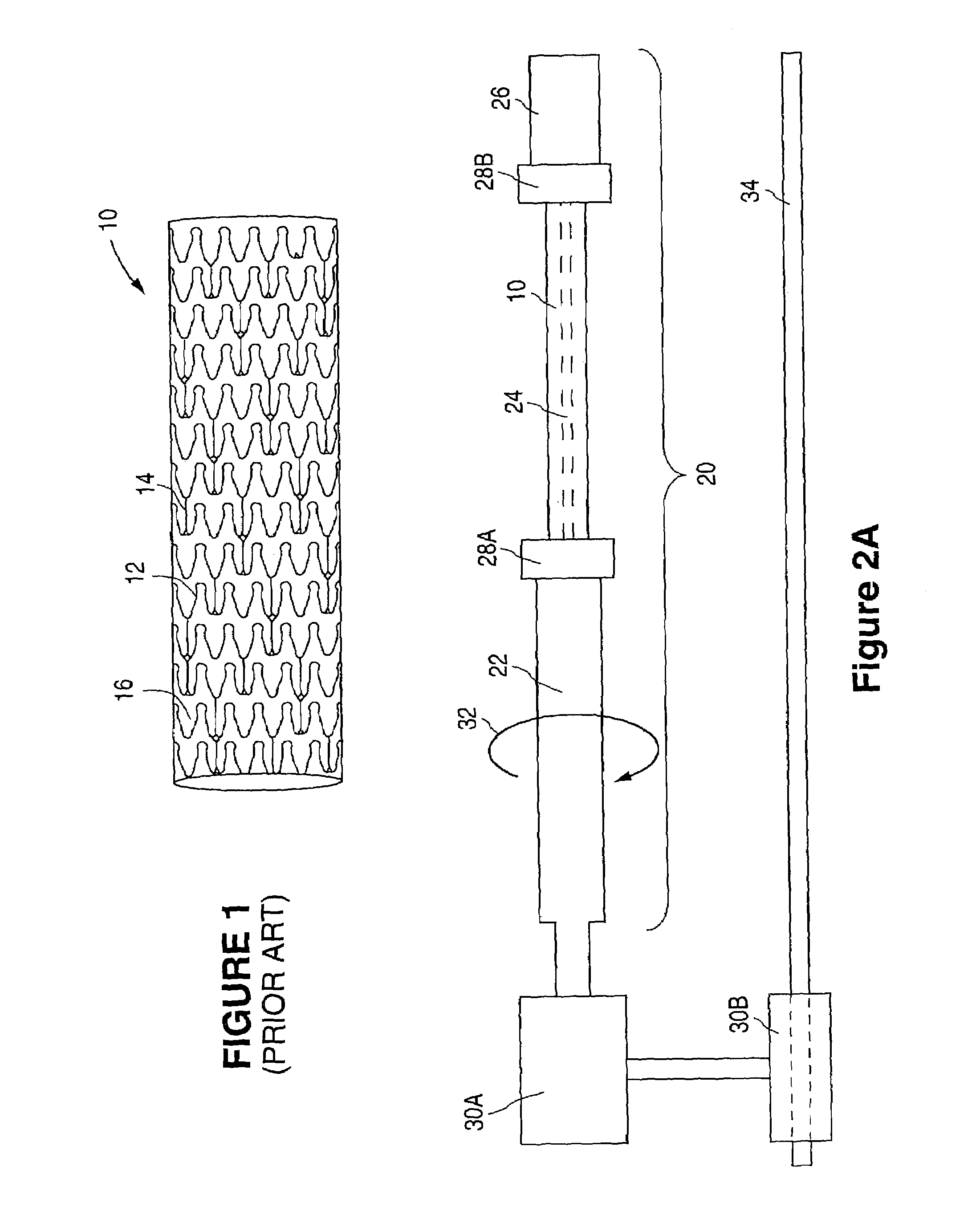
[0022]Referring to FIG. 2A, a mounting assembly 20 for supporting stent 10 is illustrated to include a support member 22, a mandrel 24, a lock member 26, and shields 28A and 28B. Support member 22 can connect to a motor 30A so as to provide rotational motion about the longitudinal axis of stent 10, as depicted by arrow 32, during the coating process. Another motor 30B can also be provided for moving support member 22 in a linear direction, back and forth, along a rail 34.

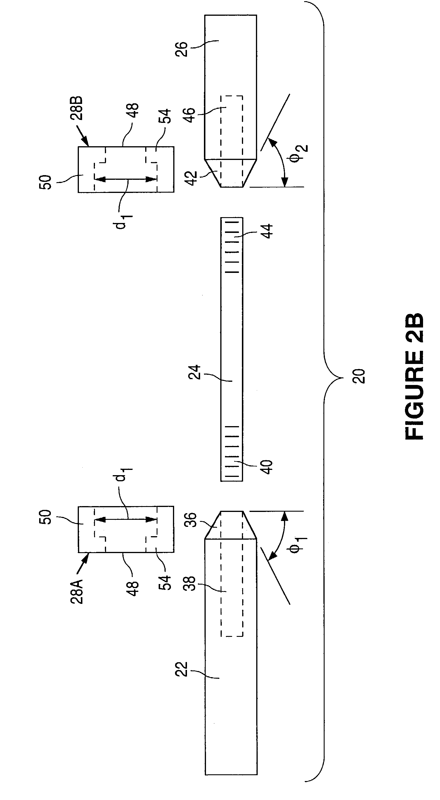
[0023]Referring to FIG. 2B, support member 22 includes a coning end portion 36, tapering inwardly at an angle φ1 of about 15° to about 75°, more narrowly from about 30° to about 60°. By way of example, angle φ1 can be about 45°. In accordance with one embodiment, mandrel 24 can be permanently affixed to coning end portion 36. Alternatively, support member 22 can include a bore 38 for receiving a first end 40 of mandrel 24. First end 40 of mandrel 24 can be threaded to screw into b...


PUM

PropertyMeasurementUnit
Lengthaaaaaaaaaa
Areaaaaaaaaaaa

Abstract

A stent mounting device and a method of coating a stent using the device are provided.

Description

CROSS REFERENCE [0001]This is a divisional application of U.S. Ser. No. 09 / 896,436, which was filed on Jun. 28, 2001 and issued as U.S. Pat. No. 6,565,659.BACKGROUND OF THE INVENTION[0002]1. Field of the Invention[0003]This invention relates to a stent mounting device and a method of coating a stent using the device.[0004]2. Description of the Background[0005]Blood vessel occlusions are commonly treated by mechanically enhancing blood flow in the affected vessels, such as by employing a stent. Stents act as scaffoldings, functioning to physically hold open and, if desired, to expand the wall of the passageway. Typically stents are capable of being compressed, so that they can be inserted through small lumens via catheters, and then expanded to a larger diameter once they are at the desired location. Examples in the patent literature disclosing stents include U.S. Pat. No. 4,733,665 issued to Palmaz, U.S. Pat. No. 4,800,882 issued to Gianturco, and U.S. Pat. No. 4,886,062 issued to W...

Claims


Application Information

Patent Timeline
IPC IPC(8): A61L27/00A61F2/00A61F2/06A61F2/90A61L31/10B05B13/02B05C11/08
CPCA61L31/10B05B13/0228B05C11/08A61F2/0077A61F2/91
Inventor PACETTI, STEPHEN D.VILLAREAL, PLARIDEL K.
Owner ABBOTT CARDIOVASCULAR
Learn More