Goniophotometer

a goniophotometer and sphere technology, applied in the field of goniophotometers, can solve the problems of unacceptably major changes in the photometric characteristics of light sources, the measurement time for determining the light flux and the luminance intensity distribution is relatively long, and the use of a sphere photometer is relatively problemati

Active Publication Date: 2007-08-14
PATENT TREUHAND GESELLSCHAFT FUR ELECTRIC GLUEHLAMPEN MBH
View PDF4 Cites 7 Cited by
  • Summary
  • Abstract
  • Description
  • Claims
  • Application Information

AI Technical Summary

Benefits of technology

[0013]In contrast, the invention is based on the object of providing a goniophotometer which allows the measurement time to be shortened or allows the measurement of different physical variables of optical radiation with minimal hardware complexity.

Problems solved by technology

In practice, the use of a sphere photometer is relatively problematic, since adequate measurement accuracy is ensured only after complex calibration of the sphere photometer and with the environmental conditions remaining constant and with low air humidity.
a) The light / radiation source is rotated about two axes (vertical and horizontal) with the measurement appliance head stationary. However, it has been found that the rotation about a horizontal axis results in an unacceptably major change in the photometric characteristics of the light source.
b) The light / radiation source and the measurement appliance head are each rotated in their own right about a vertical axis (source) and are moved on a circular path (measurement appliance head) about a horizontal axis. However, the rotations of the light / radiation source must be carried out very slowly in order to avoid changes in the photometric characteristics.
c) The measurement appliance head is moved on a family of circular paths along the envelope surface of a sphere with the light / radiation source stationary. Any desired mounting position of the light / radiation source and its fixed position during the measurement are in this case made possible, for example, by a complex universally jointed goniophotometer, as is described at www.ptb.de / de / org / 4 / 41 / 412 / kalibrierung.htm. In this case, the light / radiation source is held in a predetermined mounting position via an outer frame, while the measurement appliance head (photometer) is guided via two inner frames, which are connected to one another in a universally-jointed manner. A universally-jointed goniophotometer such as this can be produced only with very major hardware complexity. A further disadvantage of the solutions described above is that the measurement time for determination of the light flux and of the luminance intensity distribution is relatively long and, for example, this may take 80 minutes.
A further disadvantage of the known solutions is that different measurement appliance heads must be used to measure different variables, for example the luminance intensity distribution, the three-dimensional color distribution and the luminance distribution, so that a number of measurements must be carried out successively in order to record the individual variables.
A goniophotometer such as this is used, for example, to provide the light flux unit and, owing to its complex structure and the stringent software and hardware requirements, is very expensive, and is thus suitable only for research into fundamentals and for use at the PTB.

Method used


Image

  • Goniophotometer
  • Goniophotometer
  • Goniophotometer

Examples


Embodiment Construction

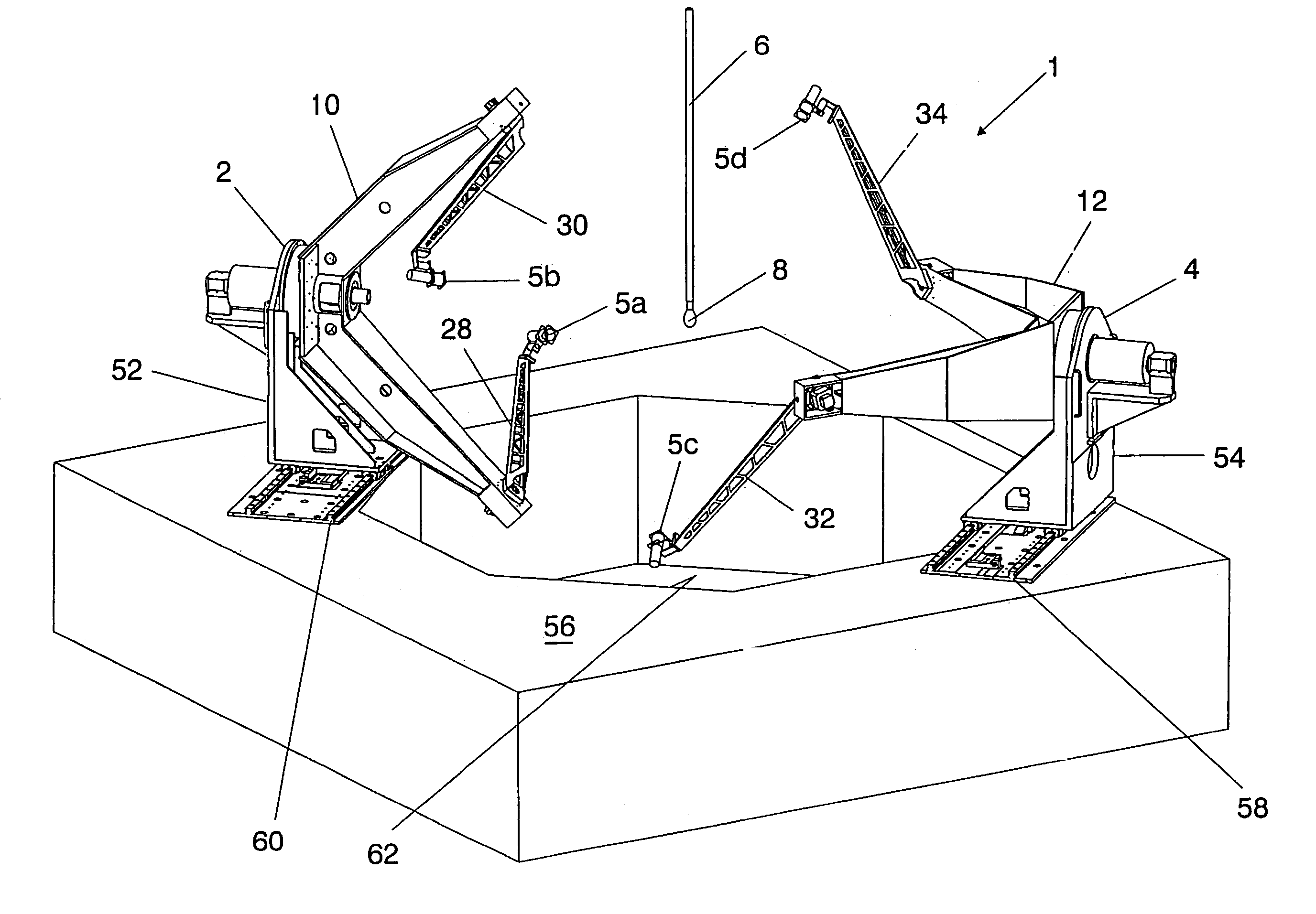
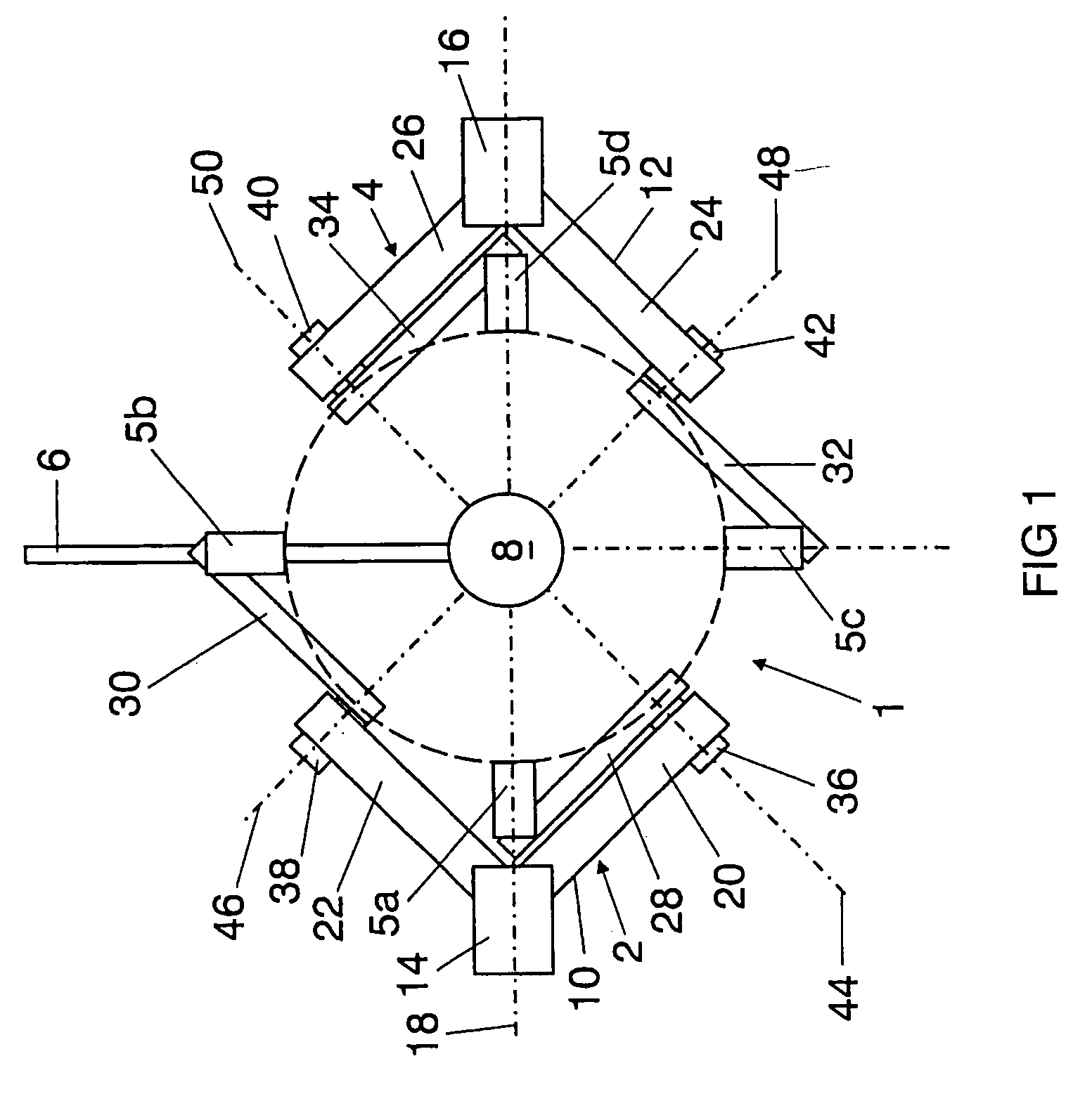
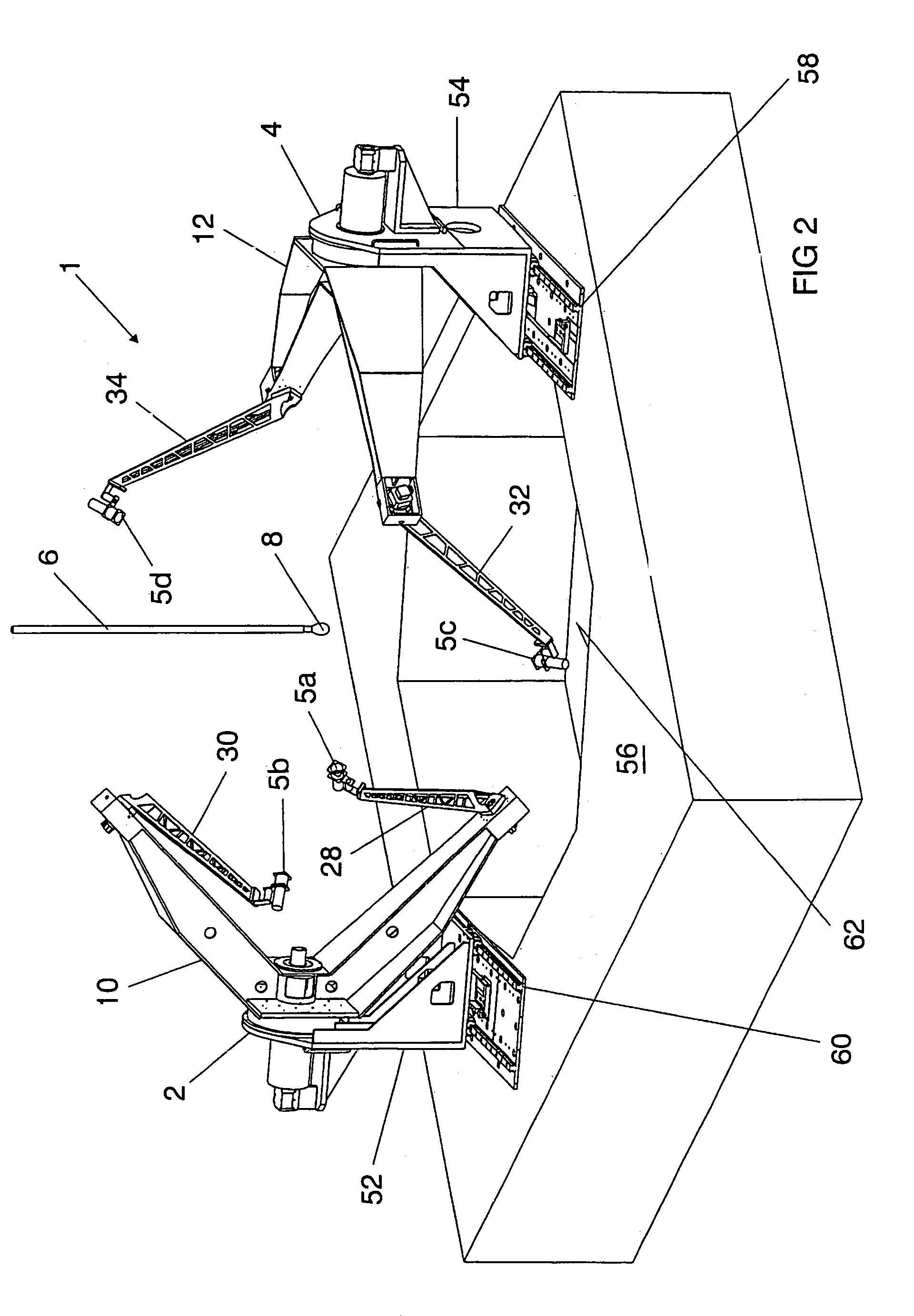
[0040]FIG. 1 shows a schematic illustration of a hemispherical goniophotometer 1 which essentially comprises two appliance units 2, 4 and a measurement object holder 6 which positions a light or radiation source, for example a lamp 8, between the two appliance units 2, 4.

[0041]Each appliance unit 2, 4 is fitted with two measurement heads 5a, 5b and 5c, 5d, respectively, with the kinematics being designed such that the two measurement heads 5a, 5b; 5c, 5d of the appliance units 2, 4 can each be moved along an envelope surface of a hemisphere. The hemispheres which are covered by the two appliance units 2, 4 are then added together to form a complete sphere, as is indicated by dashed lines in FIG. 1.

[0042]Each appliance unit 2, 4 has an approximately V-shaped respective rotating arm 10 or 12, which arms are in each case mounted by means of a main drive 14 or 16, respectively, such that they revolve around a common rotation axis 18 which runs through the lamp 8, which is held at its mo...


PUM


Abstract

A hemispherical goniophotometer is disclosed, in which two pivoting arms are articulated on a revolving rotating arm and are each fitted with a measurement head. The geometry of the arrangement is chosen such that the measurement heads can move along the envelope surface of a hemisphere during rotating of the rotating arm through 360° and pivoting of the pivoting arms through 180°.

Description

TECHNICAL FIELD[0001]The invention relates to a goniophotometer for measurement of photometric, spectroradiometric and / or colorimetric variables of the optic radiation from a light / radiation source which is held at a mounting position by a measurement object holder, having at least one measurement head which points at the light / radiation source and which, in order to record the variable, can be moved by means of a guide device, which is driven by a drive, along a predetermined movement path, preferably on an envelope surface of a sphere or hemisphere around the light / radiation source.BACKGROUND ART[0002]Either an Ulbricht sphere photometer or a goniophotometer is used in the normal manner in order to measure the light flux of a light / radiation source.[0003]The sphere photometer comprises a hollow sphere with an internal surface which is painted matt-white and produces multiply diffuse reflections of the light from a light source which is fitted in the interior, so that each area ele...

Claims


Application Information

Patent Timeline
Patent Type & Authority Patents(United States)
IPC IPC(8): G01J1/00G01J1/42G01J1/60G01J3/30
CPCG01J1/04G01J1/0403G01J1/0242
Inventor BINDER, ULRICHSAUTER, GEORGSTEUDTNER, WALTERTREBBIN, GERHARDWAGNER, NORBERT
Owner PATENT TREUHAND GESELLSCHAFT FUR ELECTRIC GLUEHLAMPEN MBH
Why Eureka
Try Eureka