
Estimating optical transmission system penalties induced by polarization mode dispersion (PMD)

a technology of polarization mode and optical transmission system, which is applied in the direction of optical elements, optical apparatus testing, instruments, etc., can solve the problems of thwarting system performance predictions, reducing system performance, and conventional systems not being able to readily isolate the causes of performance degradation

Inactive Publication Date: 2007-08-14
AMERICAN TELEPHONE & TELEGRAPH CO
View PDF9 Cites 15 Cited by
  • Summary
  • Abstract
  • Description
  • Claims
  • Application Information

AI Technical Summary

Problems solved by technology

Other sources that can degrade system performance include, for example, chromatic dispersion, multi-path interference and nonlinear effects.
When a fiber's performance has been inadequate or failing, conventional systems have not been able to readily isolate the causes of any performance degradation, or measure the relative contributions of the degradation sources.
This inability to readily diagnose the problem source(s) has thwarted predictions of system performance and prevented efficient and focused attempts to correct performance problems.

Method used


Image

  • Estimating optical transmission system penalties induced by polarization mode dispersion (PMD)
  • Estimating optical transmission system penalties induced by polarization mode dispersion (PMD)
  • Estimating optical transmission system penalties induced by polarization mode dispersion (PMD)

Examples


Embodiment Construction

[0026]In describing embodiments illustrated in the drawings, specific terminology is employed for the sake of clarity. However, the invention is not intended to be limited to the specific terminology so selected, and it is to be understood that each specific element includes all technical equivalents that operate in a similar manner to accomplish a similar purpose. Various terms that are used in this specification are to be given their broadest reasonable interpretation when used to interpret the claims.

[0027]Moreover, features and procedures whose implementations are well known to those skilled in the art are omitted for brevity. For example, initiation and termination of loops, and the corresponding incrementing and testing of loop variables, may be only briefly mentioned or illustrated, their details being easily surmised by skilled artisans. Thus, the steps involved in methods described herein may be readily implemented by those skilled in the art without undue experimentation.

[...


PUM

PropertyMeasurementUnit
lengthsaaaaaaaaaa
lengthsaaaaaaaaaa
wavelengthaaaaaaaaaa

Abstract

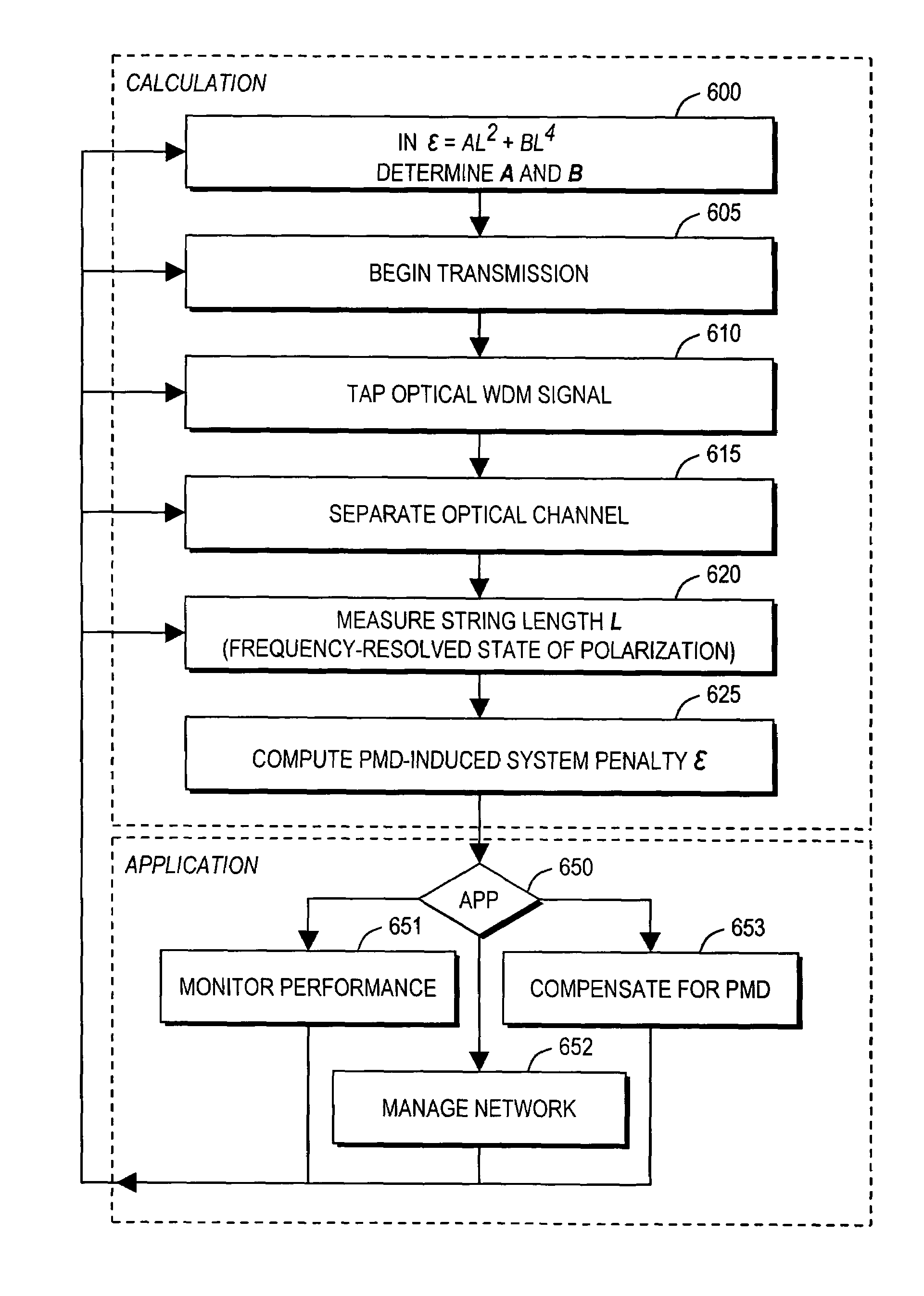
Polarization mode dispersion (PMD) induced system penalty ε is determined from optical characteristics of an optical wavelength division multiplexed (WDM) signal that is carried on a network. The method involves tapping the optical WDM signal, separating an optical channel from the tapped optical WDM signal, performing a frequency-resolved state of polarization (SOP) measurement on the channel, and computing the PMD-induced system penalty as ε=AL2+BL4, in which A and B are predetermined parameters and L is an SOP string length based on the SOP measurement.

Description

CROSS-REFERENCE TO RELATED APPLICATION[0001]This application claims priority to U.S. provisional application 60 / 699,107, filed Jul. 14, 2005, which is incorporated herein by reference in its entirety.[0002]This application may be considered to be related to co-pending U.S. application Ser. No. 10 / 825,529, filed Apr. 15, 2004 now U.S. Pat. No. 7,174,107, entitled Method and Apparatus for Measuring Frequency-Resolved States of Polarization of a Working Optical Channel Using Polarization-Scrambled Heterodyning and having common inventorship and ownership with the present patent application. This patent application is incorporated herein by reference.BACKGROUND[0003]1. Field of the Invention[0004]This invention relates to arrangements for measuring polarization mode dispersion (PMD) in optical communication fibers. More specifically, the invention relates to arrangements for determining which portion of fiber communication system penalty is induced by first-order and all-order PMD.[0005...

Claims


Application Information

Patent Timeline
Patent Type & Authority Patents(United States)
IPC IPC(8): G01N21/00
CPCG01M11/336G02B6/278H04B10/07951H04B10/2569
Inventor BORODITSKY, MIKHAILBRODSKY, MIKHAILFRIGO, NICHOLAS J.MAGILL, PETER
Owner AMERICAN TELEPHONE & TELEGRAPH CO
Learn More