
Synthesis of metamaterial ferrites for RF applications using electromagnetic bandgap structures

a technology of rf and ferrites, applied in the direction of antennas, electrical equipment, etc., can solve the problems of serious degradation of the properties of conventional ferrite materials, 1 ghz

Inactive Publication Date: 2007-08-14
PENN STATE RES FOUND
View PDF21 Cites 85 Cited by
  • Summary
  • Abstract
  • Description
  • Claims
  • Application Information

AI Technical Summary

Benefits of technology

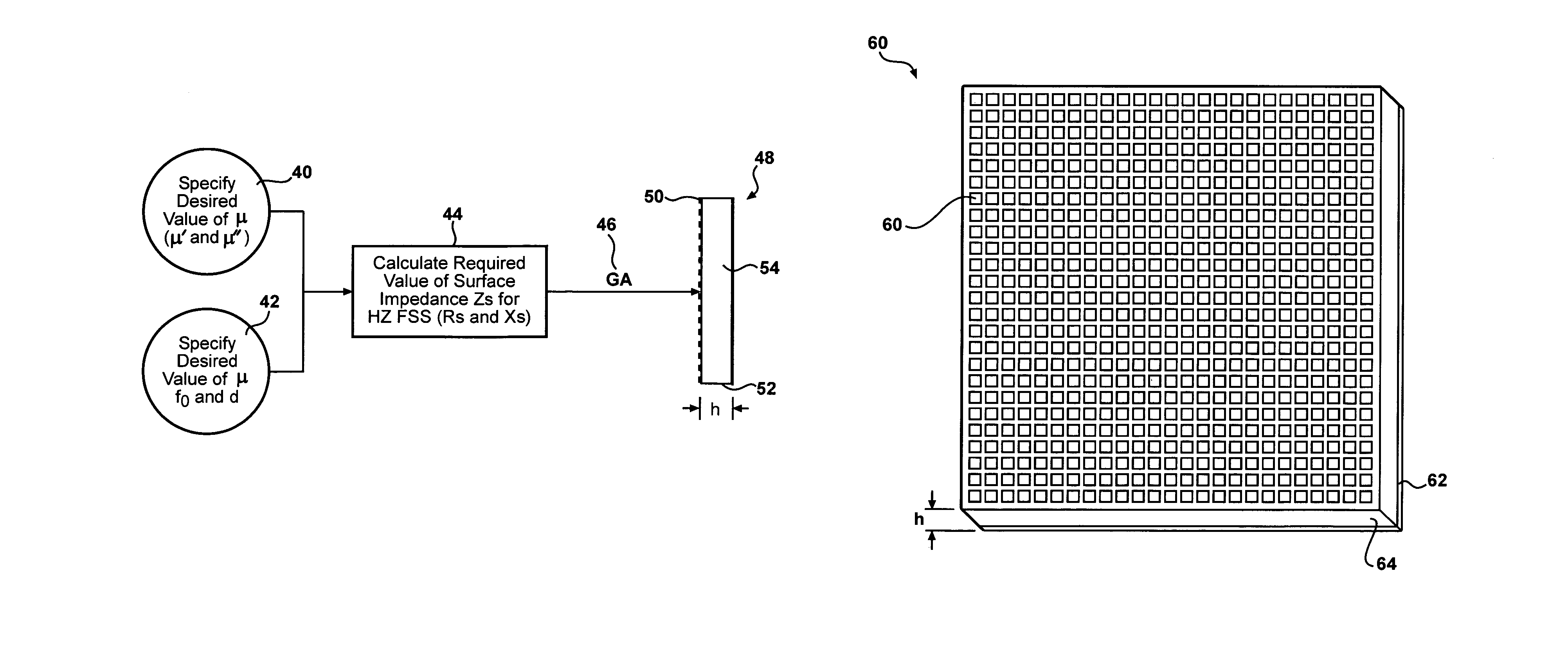
This patent describes a method for designing a metamaterial ferrite using Electromagnetic Bandgap (EBG) structures. These structures can be thought of as a magnetic material slab with a frequency-dependent permeability. By optimizing the surface impedance of the structure, a metaferrite with desired magnetic properties can be realized. The design procedure allows for low-loss negative permeability metaferrites, which can be used in applications such as left-handed or double-negative media. Overall, this patent presents a novel approach for designing high-quality metamaterial ferrites.

Problems solved by technology

However, it is well known that the properties of conventional ferrite materials are seriously degraded for frequencies above 1 GHz.

Method used


Image

  • Synthesis of metamaterial ferrites for RF applications using electromagnetic bandgap structures
  • Synthesis of metamaterial ferrites for RF applications using electromagnetic bandgap structures
  • Synthesis of metamaterial ferrites for RF applications using electromagnetic bandgap structures

Examples


example

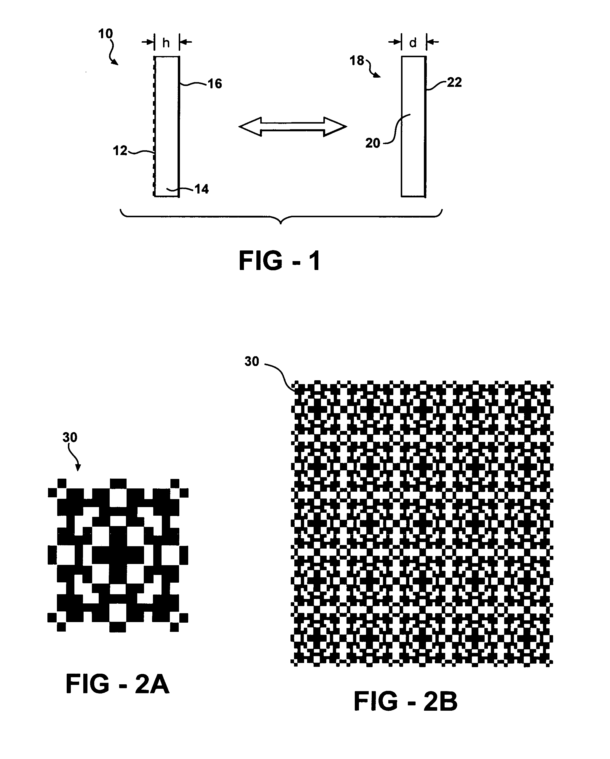
[0034]Application of the above equations is illustrated using a HZ-FSS structure developed to have an AMC condition near 1.575 GHz. This structure has not been optimized for metaferrite use, but is discussed here as an illustrative example. FIGS. 2A and 2B show the HZ-FSS geometry. FIG. 2A shows the unit cell geometry, and FIG. 2B shows the screen geometry. The dielectric constant of the substrate material in this case was εr=13−j0.025 with a thickness of 3.175 mm. The unit cell measures 1.849 cm by 1.849 cm.

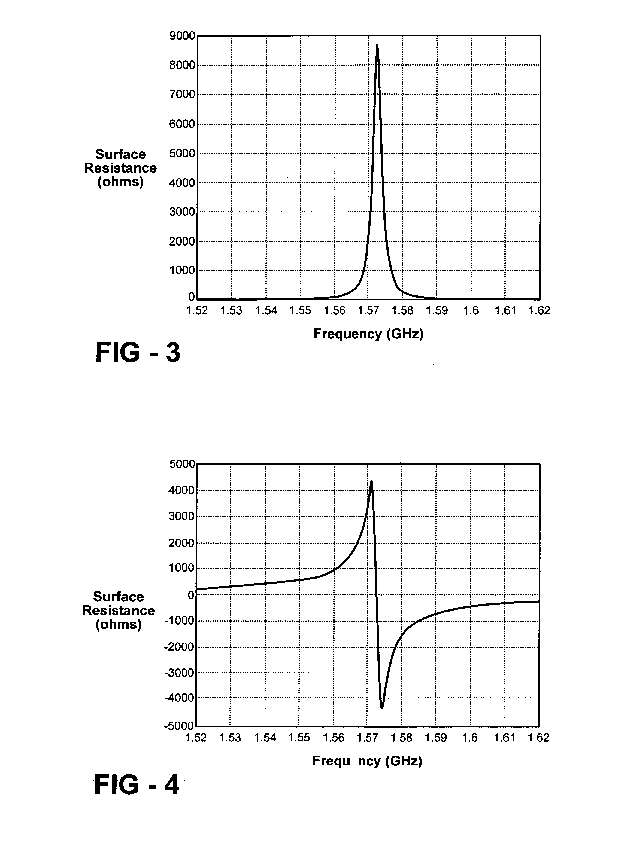
[0035]The surface impedance of such a structure can be routinely calculated using available software applications. FIGS. 3 and 4 illustrate the surface impedance near the resonant frequency of the structure shown in FIG. 2. FIG. 3 shows the surface resistance, and FIG. 4 shows the surface reactance.

[0036]The surface resistance and reactance data shown in FIGS. 3 and 4 may be used in conjunction with equations (6) and (7) to derive the characteristic curves for μr′ and μr″.

[0037]...


PUM


Abstract

By configuring a high impedance frequency selective surface (HZ-FSS) structure for the appropriate values of surface impedance (surface resistance and surface reactance), a high frequency artificial ferrite metamaterial can be synthesized with almost any desired value of real and imaginary permeability. Materials with these properties have not previously been physically realizable at frequencies above 1 GHz.

Description

REFERENCE TO RELATED APPLICATION[0001]This application claims priority from U.S. Provisional Patent Application Ser. No. 60 / 440,118, filed Jan. 14, 2003, the entire content being incorporated herein by reference.FIELD OF THE INVENTION[0002]The present invention relates generally to metamaterial structures.BACKGROUND OF THE INVENTION[0003]Thin ferrite films have advantageous properties, such as absorption of electromagnetic radiation. However, it is well known that the properties of conventional ferrite materials are seriously degraded for frequencies above 1 GHz. There are numerous applications for materials or structures that provide the properties of a thin ferrite film at frequencies above those conventionally available.[0004]Metamaterials are generally multi-component structures that can provide advantageous physical properties compared with uniform bulk materials. Such structures are also sometimes called engineered materials. A metamaterial ferrite is a metamaterial providing ...

Claims


Application Information

Patent Timeline
Patent Type & Authority Patents(United States)
IPC IPC(8): H01Q15/02H01Q15/00
CPCH01Q15/0086
Inventor WERNER, DOUGLAS H.KERN, DOUGLAS J.
Owner PENN STATE RES FOUND
Learn More