
Force feedback interface device with sensor

Inactive Publication Date: 2007-08-07
IMMERSION CORPORATION
View PDF169 Cites 80 Cited by
  • Summary
  • Abstract
  • Description
  • Claims
  • Application Information

AI Technical Summary

Benefits of technology

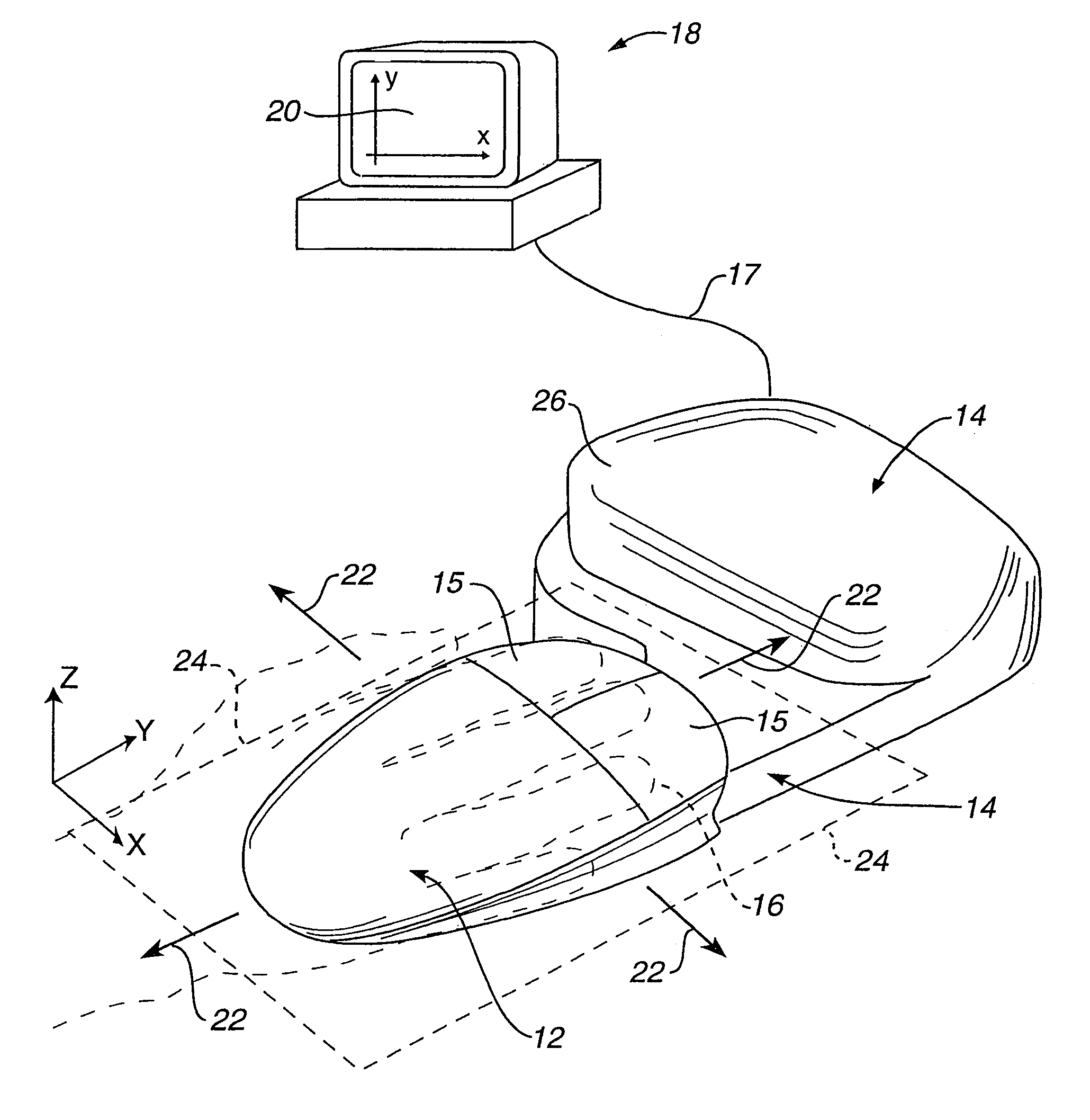
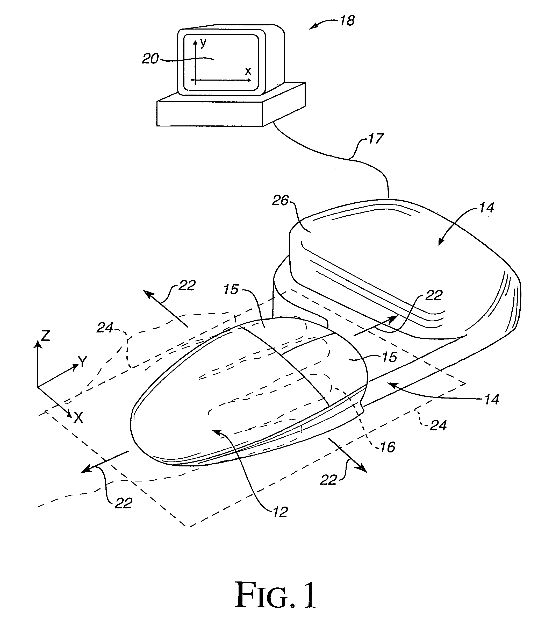
[0009]The present invention is directed to a mouse interface which is connected to a host computer and provides realistic force feedback to a user. The interface device includes low cost, compact components that provide a convenient mouse interface for a desktop.
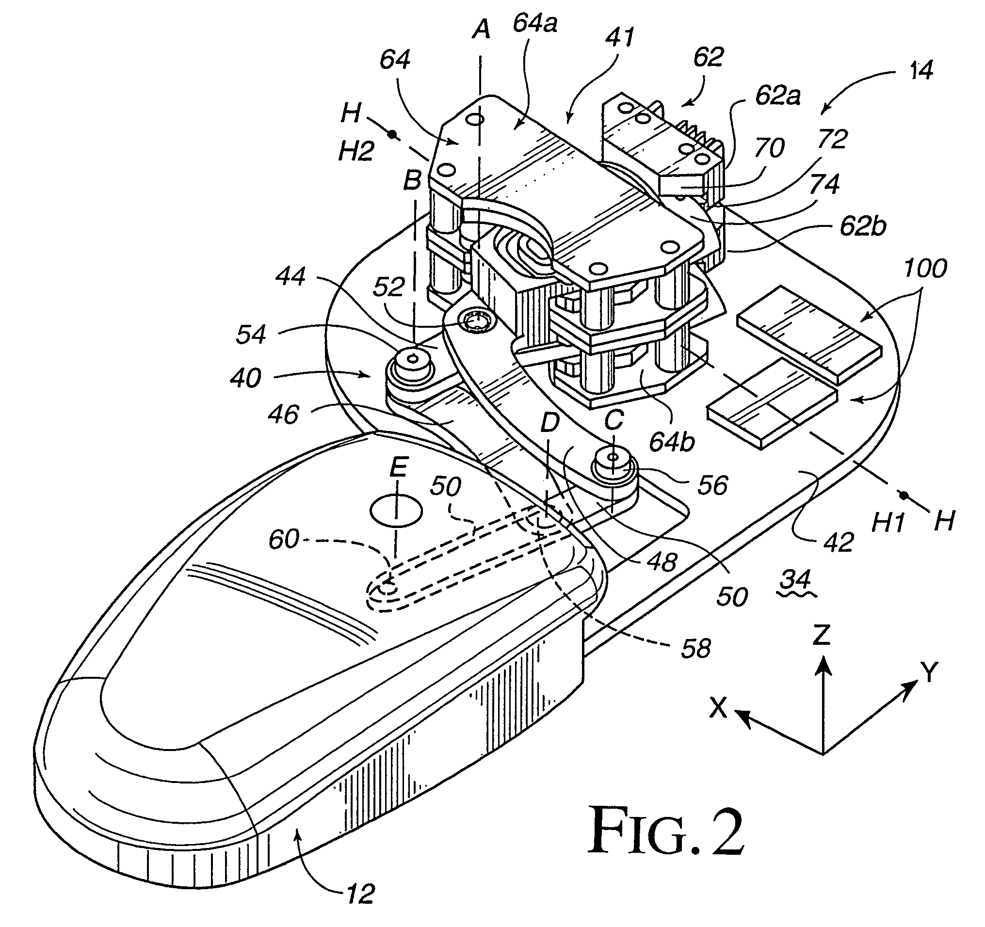
[0011]The planar linkage may include four members coupled to a ground member, where a first base member is rotatably coupled to the ground member, a link member is rotatably coupled to the base member, a second base member is rotatably coupled to the ground member, and an object member is rotatably coupled to the link member and the second base member. The mouse object is coupled to the object member and preferably may rotate with respect to the object member to allow the user easy handling of the mouse. The members of the linkage are coupled together by bearings of the present invention, which may be ball bearing assemblies, snap together bearings, snap together bearings including ball bearings, or V-shaped bearings.
[0012]The coils of the actuators are preferably integrated in the members of the linkage, for example the base members of the linkage, and move through magnetic fields provided by the grounded portions. In addition, the grounded magnet portions of the actuators are coupled together in one embodiment, such that a common flux path between the magnet portions is shared by both magnet portions. In a preferred configuration, the first and second base members are coupled to a rotation point at a mid point of the base members, where one end of each base member integrates said coil such that the coil is spaced from the rotation point of said member, thereby providing mechanical advantage to forces generated by the actuator on the base members.
[0014]The mouse object is preferably rotatably coupled to the object member to allow convenient use of the mouse for the user such that the mouse object rotates about an axis of rotation though the object member, said axis of rotation being perpendicular to the ground surface. A stop mechanism limits movement of the mouse object in the planar workspace to a desired area, and can include a guide opening provided in the ground surface and a guide pin coupled to the linkage that engages sides of the guide opening to provide the movement limits. A safety switch can be included that causes the actuators to be deactivated when the user is not contacting the mouse object. A local microprocessor, separate from the host computer system, is included in the interface device and may provide local control over sensing and outputting forces to relieve the computational burden on the host computer. The interface device can also include a support such as a low friction Teflon pad, roller, or other member separate from the linkage and coupled between the mouse object and the ground surface for providing extra support to the mouse. An indexing feature of the present invention allows the user to change the offset between the position of the mouse object and the location of a displayed cursor on a display screen.
[0015]The method and apparatus of the present invention provides a force feedback mouse interface that allows a user to conveniently interface with a host computer application program. The actuators, sensors, and linkage of the device, in the embodiments described, provide a compact, simple, low-cost design that outputs realistic forces on the user and accurately tracks the user's motions in the provided workspace, and is well suited for the consumer market.

Problems solved by technology

Current force feedback joystick devices may allow realistic and effective forces to be transmitted to a user; however, the standard joystick device is well-suited for such uses as controlling an aircraft or other simulated vehicle in a simulation or game, first-person perspective virtual reality applications, or other rate-control tasks and is not well suited to position control tasks such as controlling a pointer or cursor in a graphical user interface.
A problem with the currently-available position control interface devices is that none of them offer realistic force feedback.
A mouse is not easily provided with force feedback since the mouse must be moved in a planar workspace and is not easily connected to actuators which provide the force feedback.
Controllers as trackballs and tablets are even less well suited for force feedback than a mouse controller due to their free-floating movement.
A mouse can be coupled to actuators from a side linkage, but a compact, low cost, and conveniently-positioned mechanism allowing free movement of a mouse as well as providing realistic force feedback for the mouse has not been available in the consumer market.

Method used


Image

  • Force feedback interface device with sensor
  • Force feedback interface device with sensor
  • Force feedback interface device with sensor

Examples


embodiment 193

[0111]FIG. 4j is a perspective view of an alternate embodiment 193′ of the sensor 193 of FIG. 4i. Embodiment 193′ includes a rotating arm 195 and detector 197 as described in FIG. 4i. In addition, a flexible fiber optic cable 199 or similar flexible light guide is coupled between the emitter 194 and the arm 195. Fiber optic cable 199 guides a light beam 189 from emitter 194 and along the cable's length, where the transmission of light through such a cable is well known to those skilled in the art. The beam is guided to arm 195, where the beam 189 is directed onto detector 197 as in FIG. 4i. The cable 199 may flex as the arm 195 rotates about axis F3. This embodiment allows the emitter 194 to be grounded as well as the detector 197, thus simplifying assembly and reducing the manufacturing cost of the device.

[0112]FIG. 5a is a perspective view and FIG. 5b is a side elevational view of one embodiment of a ball bearing assembly 200 suitable for use for rotatably connecting the members o...

embodiment 224

[0115]FIGS. 5d1 and 5d2 are perspective views of an alternate embodiment 224 of the snap bearings 216 and 218 of FIG. 5c. As shown in FIG. 5d1, bearing 224 includes a fork 225 provided, in the example shown, on member 48 (the bearing 224 can be provided on other members of linkage 40 or 40′ as well). Fork 225 includes two prongs 226 that each include a cavity 227 for receiving a corresponding assembly of bearing 224 (not shown in FIG. 5d1). Like the snap bearings 216 and 218 of FIG. 5c, a slot 228 extends from each of the cavities 227 on the prongs 226. In FIG. 5d1, bearing 58 on member 46 is a standard bearing having two prongs for holding a corresponding portion (not shown) of a bearing on the attached member.

[0116]In FIG. 5d2, member 50 has been attached to members 46 and 48. Bearing 224 couples member 48 with member 50. A bearing assembly 229 of member 50 includes two cylindrical bosses 230 at either end which “snap” into (mate with) the prongs 226 of the fork 225 on member 48 a...


PUM


Abstract

A force feedback mouse interface device connected to a host computer and providing realistic force feedback to a user. The mouse interface device includes a mouse object and a linkage coupled to the mouse that includes a plurality of members rotatably coupled to each other in a planar closed-loop linkage and including two members coupled to ground and rotatable about the same axis. Two actuators, preferably electromagnetic voice coils, provide forces in the two degrees of freedom of the planar workspace of the mouse object. Each of the actuators includes a moveable coil portion integrated with one of the members of the linkage and a magnet portion coupled to the ground surface through which the coil portion moves. The grounded magnet portions of the actuators can be coupled together such that a common flux path between the magnet portions is shared by both magnets. At least one sensor is coupled to the ground surface that detects movement of the linkage and provides a sensor signal including information from which a position of the mouse object in the planar workspace can be determined.

Description

CROSS REFERENCE TO RELATED APPLICATIONS[0001]This is a continuation application Ser. No. 09 / 401,044 filed on Sep. 22, 1999 now U.S. Pat. No. 6,191,774, in the name of Bruce M. Schena et al., which is a continuation of prior U.S. application Ser. No. 08 / 881,691 filed on Jun. 24, 1997 now U.S. Pat. No. 6,100,874 in the name of Bruce M. Schena et al., which is a continuation-in-part of U.S. application Ser. Nos. 08 / 560,091, now U.S. Pat. No. 5,805,140, filed Nov. 17, 1995, and 08 / 756,745, now U.S. Pat. No. 5,825,308, filed Nov. 26, 1996, the disclosures of which are incorporated herein by reference in their entirety.BACKGROUND OF THE INVENTION[0002]The present invention relates generally to interface devices for allowing humans to interface with computer systems, and more particularly to mechanical computer interface devices that allow the user to provide input to computer systems and provide force feedback to the user.[0003]Computer systems are used extensively in many different indus...

Claims


Application Information

Patent Timeline
IPC IPC(8): G09G5/00G09G5/08G05G9/047G06F3/00G06F3/01G06F3/038G09B23/28
CPCB25J9/1692G01B5/008G01B7/004G01B21/04G05B19/4207G05D25/02G05G9/047G06F3/016G06F3/0346G06F3/0354G06F3/03543G06F3/038G06F3/0383G09B9/28G09B23/28G09B23/285A61B19/26A63F2300/1037G05G9/04737G05G2009/0474G05G2009/04766G05G2009/0477G06F2203/015H01H2003/008A61B90/50
Inventor SCHENA, BRUCE M.ROSENBERG, LOUIS B.
Owner IMMERSION CORPORATION
Learn More