Wide frequency band planar antenna

a planar antenna and wide frequency band technology, applied in the direction of radiating element structural forms, elongated active element feeds, resonance antennas, etc., can solve the problems of preventing users from accessing the internet, limiting the use to only the vicinity of fixed locations, so as to achieve the effect of minimising reflection loss and minimising reflection loss

Active Publication Date: 2007-08-07
DELTA ELECTRONICS INC
View PDF5 Cites 5 Cited by
  • Summary
  • Abstract
  • Description
  • Claims
  • Application Information

AI Technical Summary

Benefits of technology

[0010]According to the first embodiment of the present invention, the multiple frequency broadband planar antenna of the third embodiment of the present invention further comprises an impedance-matching-adjusting stub, one end of which is short-circuited to the ground pattern through a via, and another end is connected to a joint between the elongated portion and the feeding transmission line. Additionally, the short stub serves to adjust an impedance matching between the wide frequency band planar antenna and the feeding transmission line so that a high frequency AC signal passing through the transmission line can be optimally transmitted into the planar antenna with a minimum reflection loss.
[0011]According to the second embodiment of the present invention, the wide frequency band planar antenna of the fourth embodiment of the present invention further comprises an impedance-matching-adjusting stub, one end of which is short-circuited to the ground pattern through a via, and another end of which is connected to a joint between the elongated portion and the feeding transmission line. Additionally, the short stub serves to adjust an impedance matching between the wide frequency band planar antenna and the transmission line so that a high frequency AC signal passing through the transmission line can be optimally transmitted into the planar antenna with a minimum reflection loss.

Problems solved by technology

However, the wireless WiFi LAN technology has some drawbacks that limit the use to only the vicinity of the fixed location.
These drawbacks refer to a low capacity and a short range (about several hundred meters) for wireless communication carriers, which prevents the users from accessing the internet at any place.
As a result, the laminate pattern antenna is able to operate at a wider frequency band; however, its operating frequency is about 2.4 GHz, which limits its application only to WiFi LAN, except for WiMAX MAN.
Besides, as the laminate pattern antenna has a complicated structure, its fabricating procedures are accordingly lengthy and the procedures for forming the inverted-F-shaped antenna pattern and then the inverted-L-shaped antenna pattern on both side surfaces of the PCB increases a fabricating cost.
Accordingly, the laminate pattern antenna fails to meet a compactness requirement of a planar antenna due to its laminated structure, in addition to its narrow frequency band.

Method used


Image

  • Wide frequency band planar antenna
  • Wide frequency band planar antenna
  • Wide frequency band planar antenna

Examples


Embodiment Construction

[0021]Reference will now be made in detail to a wide frequency band planar antenna, examples of which are illustrated in the accompanying drawings. Wherever possible, the same reference numbers are used in the drawings and the descriptions to refer to the same parts.

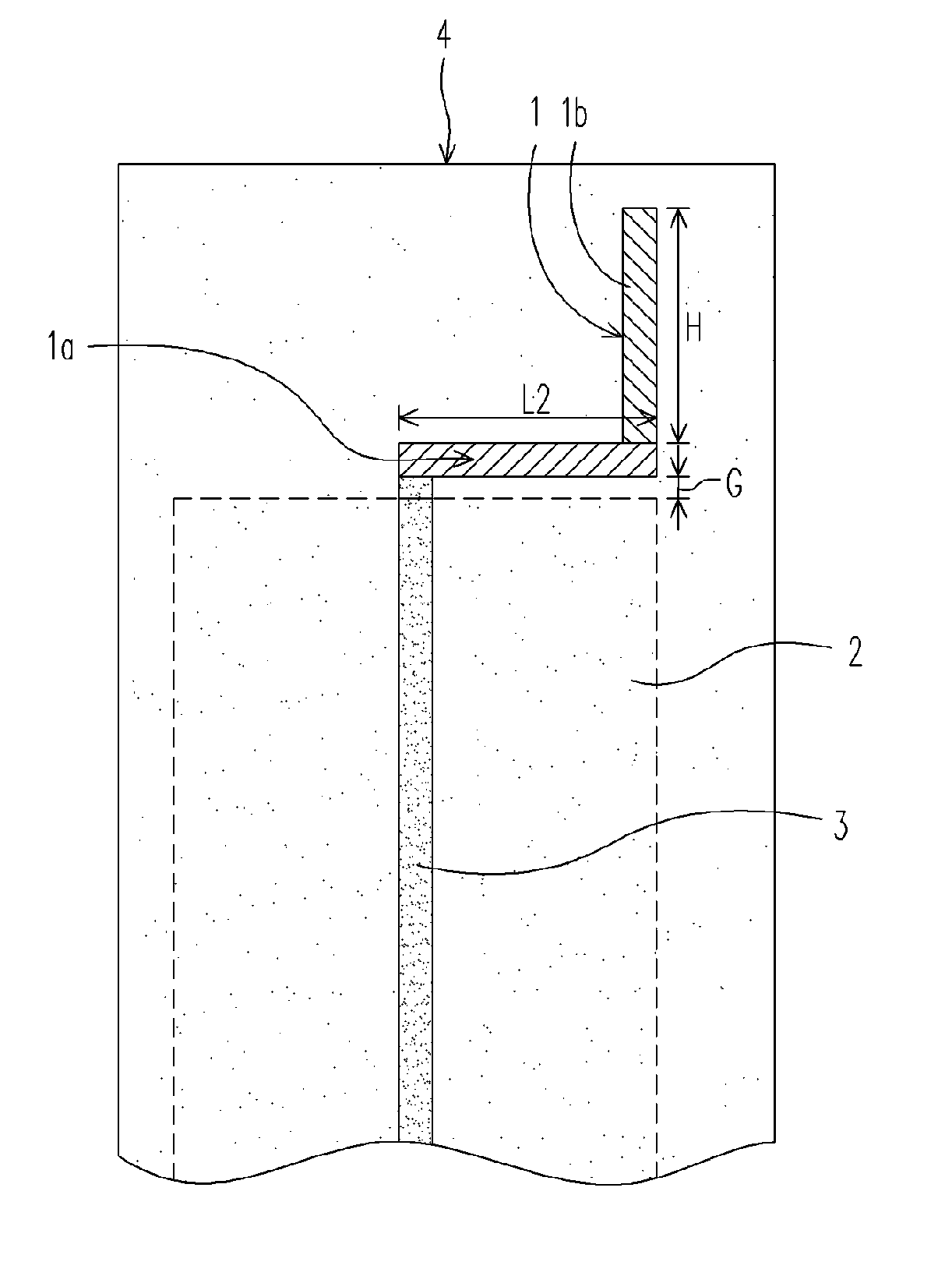
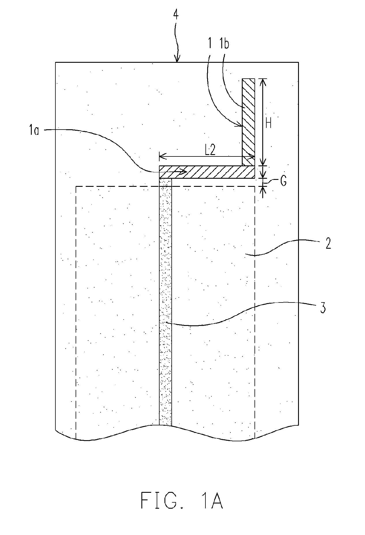
[0022]FIG. 1A shows a top view of a wide frequency band planar antenna of the first embodiment of the present invention. The wide frequency band planar antenna 1 comprises an elongated portion 1a and a body stub 1b. Besides, the elongated portion 1a and the body stub 1b form an inverted-L-shaped pattern, wherein the elongated portion 1a is substantially parallel with a circumferential edge of a ground pattern 2 for isolating, which is formed on the reverse-side surface of a circuit board 4 (surrounded by a dash line), opposite to the obverse-side surface (or referred as the component-side surface) thereof, on which the wide frequency band planar antenna and other electronic components are mounted. Moreover, there is a ga...


PUM


Abstract

A wide frequency band planar antenna comprises an elongated portion, substantially parallel to a circumferential edge of a ground pattern and comprising one end connected to a feeding transmission line, wherein there is a gap between the elongated portion and the circumferential edge of the ground pattern; a body stub and an impedance-matching-adjusting pattern for adjusting an impedance matching between the wide frequency band planar antenna and the feeding transmission line; wherein the gap value is less than 2 mm so as to enable the wide frequency band antenna to operate at a wide range of frequencies ranging from 2.3 GHz to near 6 GHz, thereby allowing the wide frequency band antenna to be applied in both WiFi LAN and WiMAX MAN.

Description

BACKGROUND OF THE INVENTION[0001]1. Field of the Invention[0002]The present invention generally relates to a planar antenna, and more particularly, to a wide frequency band planar antenna.[0003]2. Description of Related Art[0004]With the advance of wireless internet access technology, a wireless notebook computer allows users to access the internet at a fixed location where an internet station is located, such as, a train station, a university, etc., within a wireless local area network (WLAN). As a result, the wireless notebook has become a mainstream product because it allows the users to freely access the internet. In recent years, WiFi wireless Local Area Network (LAN) has been introduced, which operates at about 2.4 GHz and 5 GHz (these frequencies are referred as a communication carrier frequency modulated by data signals in any modulation technology, such as an orthogonal frequency division multiplex (OFDM) technology). However, the wireless WiFi LAN technology has some drawb...

Claims


Application Information

Patent Timeline
Patent Type & Authority Patents(United States)
IPC IPC(8): H01Q1/24H01Q5/10
CPCH01Q1/243H01Q1/38H01Q9/0421H01Q9/40H01Q9/42
Inventor CHI, SHENG-YUANCHUNG, SHYH-JONGCHEN, YU-CHENG
Owner DELTA ELECTRONICS INC
Why Eureka
Try Eureka