
Method for removing noise from nuclear magnetic resonance signals and images

a nuclear magnetic resonance and noise removal technology, applied in the field of digital signal processing techniques, noise filters, nuclear magnetic resonance spectroscopy, etc., can solve the problems of substantial increase in acquisition time, limiting the signal-to-noise ratio (snr) of nmr signals and images, and not being able to achieve the effect of reducing patient discomfor

Inactive Publication Date: 2007-08-07
KING FAHD UNIVERSITY OF PETROLEUM AND MINERALS
View PDF24 Cites 15 Cited by
  • Summary
  • Abstract
  • Description
  • Claims
  • Application Information

AI Technical Summary

Benefits of technology

[0024]These and other features of the present invention will become readily apparent upon further review of the following specification and drawings.

Problems solved by technology

The signal-to-noise ratio (SNR) of NMR signals and images is typically the limiting factor for higher data interpretation.
Signal / image averaging is typically used to increase the SNR, but this method often results in a substantial increase in the acquisition time, which may not be tolerable in many situations, particularly for unstable biological compounds where long replications are not feasible.
Further, a longer time is not desirable with regard to patient comfort, as well as avoidance of motion artifacts in medical MRI usage.
However, this truncated SVD of the observed matrix is generally no longer a Hankel matrix.
This is in contrast to bilinear distributions where difficulties are encountered in retrieving the signal from the TF-domain.

Method used


Image

  • Method for removing noise from nuclear magnetic resonance signals and images
  • Method for removing noise from nuclear magnetic resonance signals and images
  • Method for removing noise from nuclear magnetic resonance signals and images

Examples


Embodiment Construction

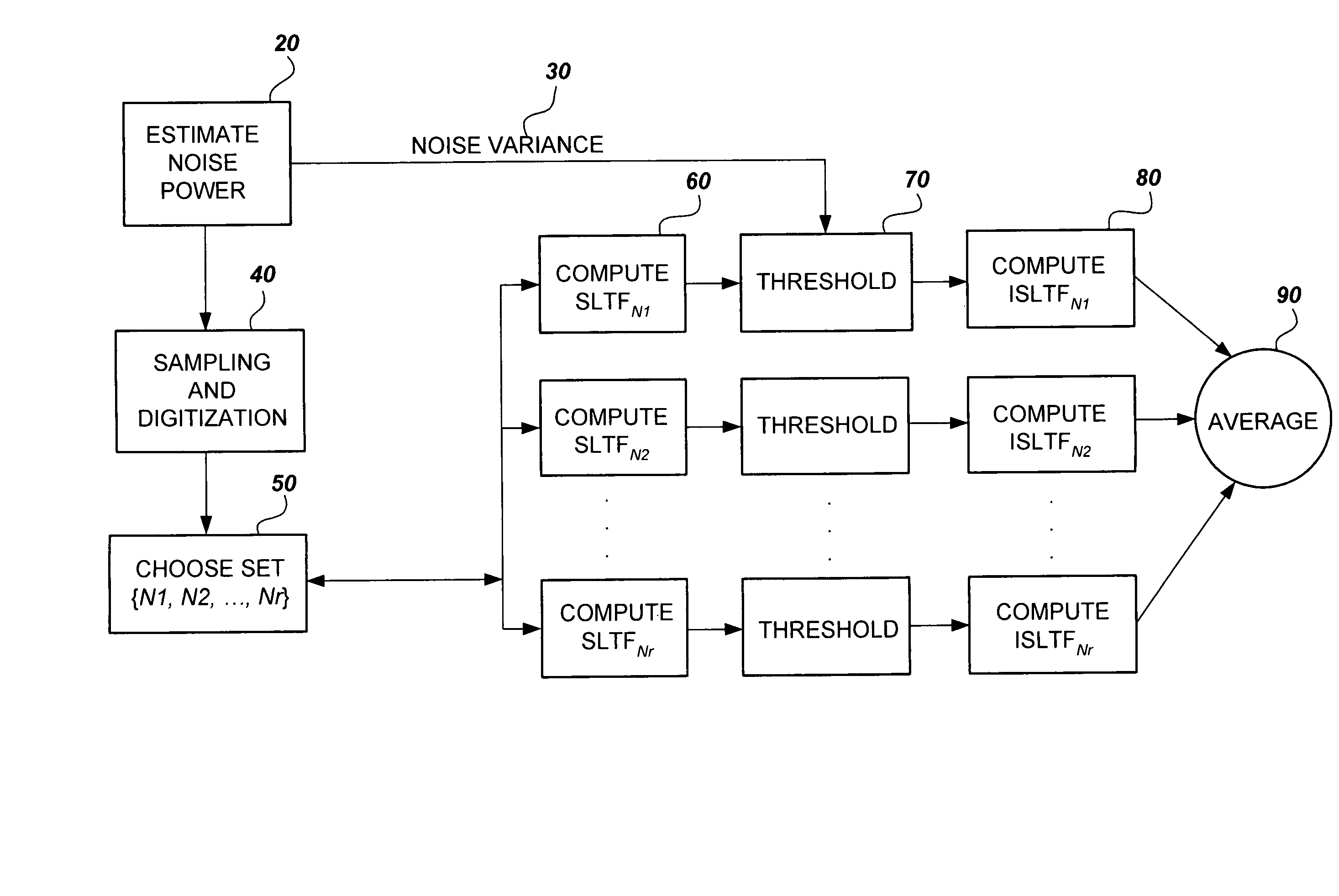
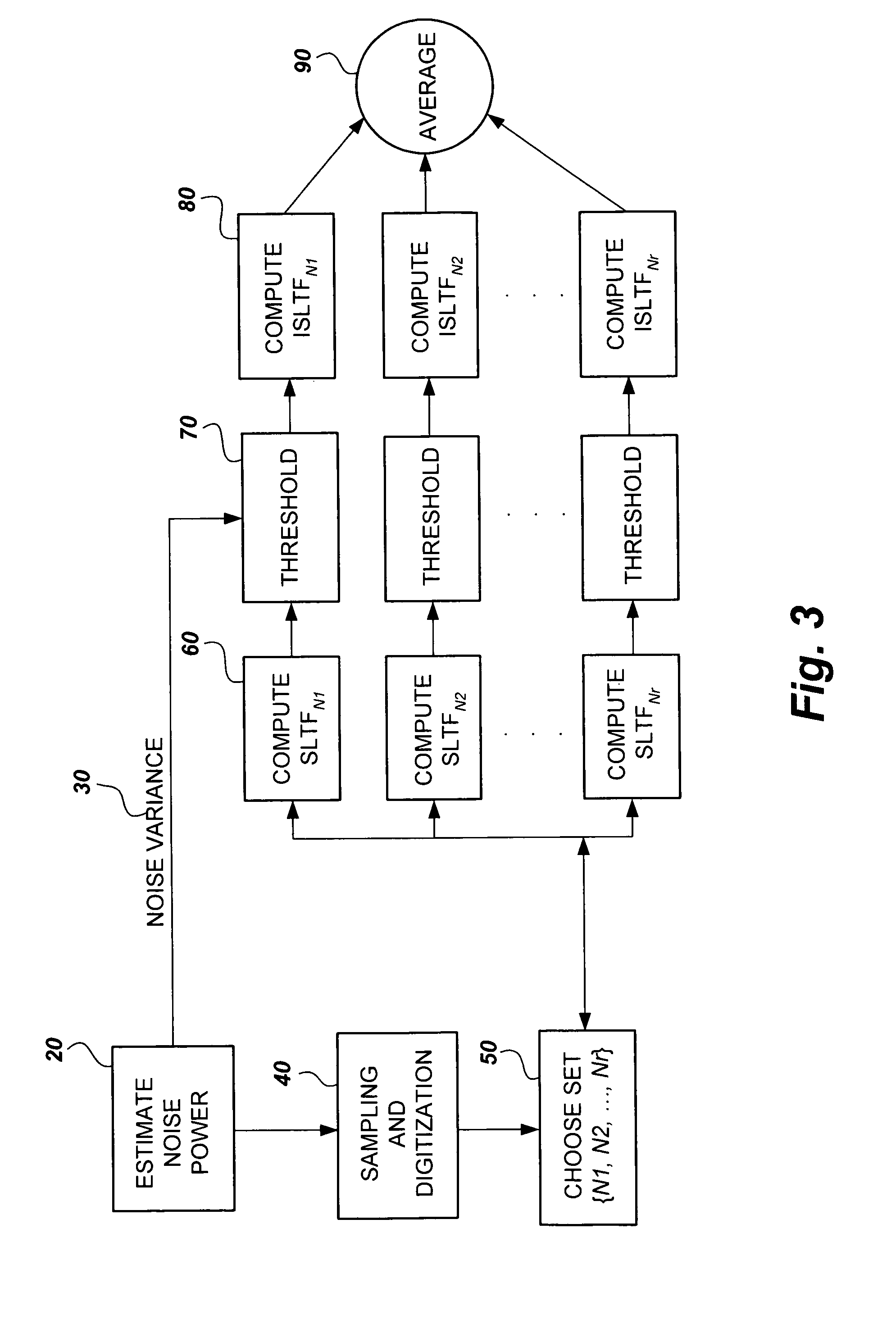
[0039]Referring to FIG. 3, a flow chart diagram representing the steps in a method for removing noise from NMR signals and images is shown. At block 20, the NMR signal or image (both and NMR spectroscopy signal and an MRI image signal ma be referred to generally as an “NMR signal” in the present application) is first processed to estimate the noise variance. An example of such processing would include providing a relatively large recording time for at least one sample. The noise variance σ would then be estimated by calculating the power of the last data points, which are entirely noise.

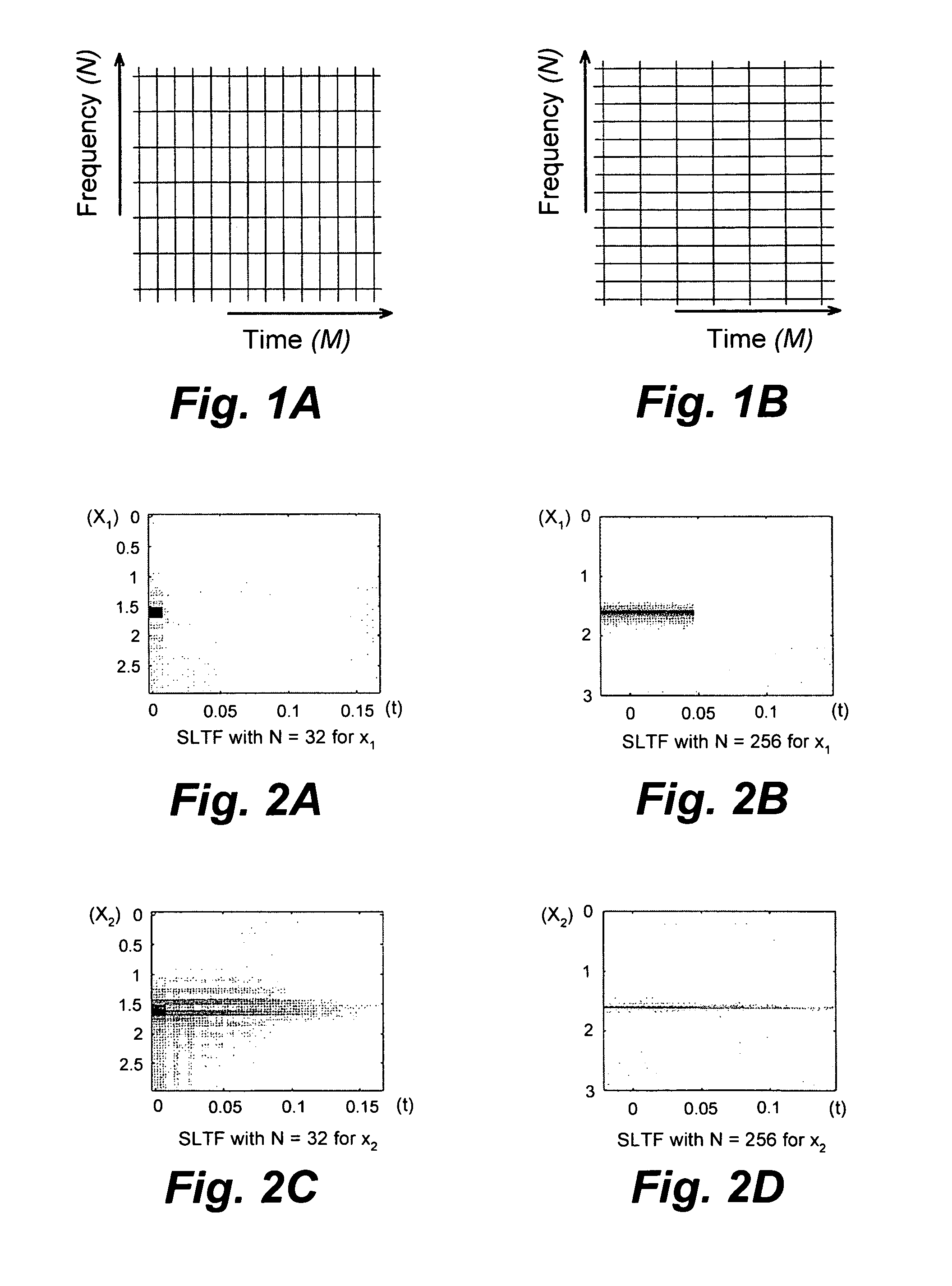
[0040]At block 40, the NMR signal / image is next sampled and digitized. At block 50, a set N={N1, N2, . . . , Nr}, of r suitable values of N is then determined according to the time span, the sampling period, etc. The stable linear time-frequency (SLTF) transform is specified by its number of analysis samples in frequency, N, which controls the time and frequency resolutions in the time-frequency (TF)...


PUM


Abstract

The method for removing noise from nuclear magnetic resonance signals and images involves removing noise from NMR signals through the application of stable linear time-frequency (SLTF) transforms. According to the method, a noise variance for a particular NMR signal is calculated and the NMR signal is sampled and digitized. A set of analysis samples that vary in the number of samples in frequency is selected so that each member of the set has a compact signal / image representation for at least one component according to the differing component relaxation times of the signal / image. Each member of the set is then processed by the SLTF to determine the transform coefficients, the coefficients are subjected to threshold value criteria to denoise the coefficients, and the inverse SLTF transform is computed for each member of the set to obtain the denoised signal. The member signals are then averaged to obtain the denoised NMR signal.

Description

BACKGROUND OF THE INVENTION[0001]1. Field of the Invention[0002]The present invention relates to digital signal processing techniques, noise filters, nuclear magnetic resonance spectroscopy, and nuclear magnetic resonance imaging, and particularly to a method for removing noise from nuclear magnetic resonance signals and images.[0003]2. Description of the Related Art[0004]Nuclear magnetic resonance (NMR) is a potentially useful and effective diagnostic tool in basic research, clinical investigation and disease diagnosis, since it provides both chemical and physiological information regarding the tissue under investigation. NMR is based upon the precession of protons when placed in a magnetic field. The precessional axis lies along the direction of the magnetic field, and the precession occurs with a frequency directly proportional to the strength of the magnetic field, with a proportionality constant unique to each atom, which is called the gyromagnetic ratio.[0005]If an oscillating...

Claims


Application Information

Patent Timeline
Patent Type & Authority Patents(United States)
IPC IPC(8): G01V3/00
CPCG01R33/56G01R33/5608
Inventor AHMED, OSAMA ABDEL-WAHHAB
Owner KING FAHD UNIVERSITY OF PETROLEUM AND MINERALS
Learn More