
Distraction device for maxillofacial surgery

a technology for dislocation devices and maxillae, which is applied in non-surgical orthopedic devices, internal osteosynthesis, medical science, etc., can solve the problems of large distractors, large devices, and large devices, and achieves low risk of infections and other complications, small inconvenience or irritation, and convenient application.

Inactive Publication Date: 2007-08-07
FACEWORKS SOLUTIONS & TECH
View PDF10 Cites 11 Cited by
  • Summary
  • Abstract
  • Description
  • Claims
  • Application Information

AI Technical Summary

Problems solved by technology

The device is large, has a complex screw, and requires fixation through the skin with long pins.
The device is large and complex and requires transmucosal fixation
This distractor is large and requires a complex surgical operation for fixation and removal under general anesthesia.
Size and construction of the device make it too bulky to be used in vertical alveolar distraction.
The use of many lateral pins could lead to damage to adjacent anatomical structures.
The use of a lengthy and bulky chamber with cylinder may be uncomfortable during the period of distraction and are too large for use in vertical alveolar distraction.
Further, it seems that the distraction screw cannot be replaced with an alternative distraction screw without removal of one or more of the brackets.
Some of the perforations are positioned in the distraction gap and interfere with the neo-osteogenic site.
The use of many lateral pins could lead to damage to adjacent anatomical structures.
The devices have sharp edges, particularly the end of the screw and the brackets, and do not have a smooth surface.
None of the devices has a guiding rail.
However, the device has a large size and is not described for vertical alveolar distraction.
The distraction screw does not push against the chamber and the screw cannot easily be replaced during the distraction.
However, the fixed bracket does not have an aperture and the device seems too bulky for vertical alveolar distraction.

Method used


Image

  • Distraction device for maxillofacial surgery
  • Distraction device for maxillofacial surgery
  • Distraction device for maxillofacial surgery

Examples


example 1

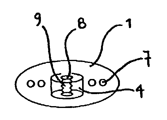
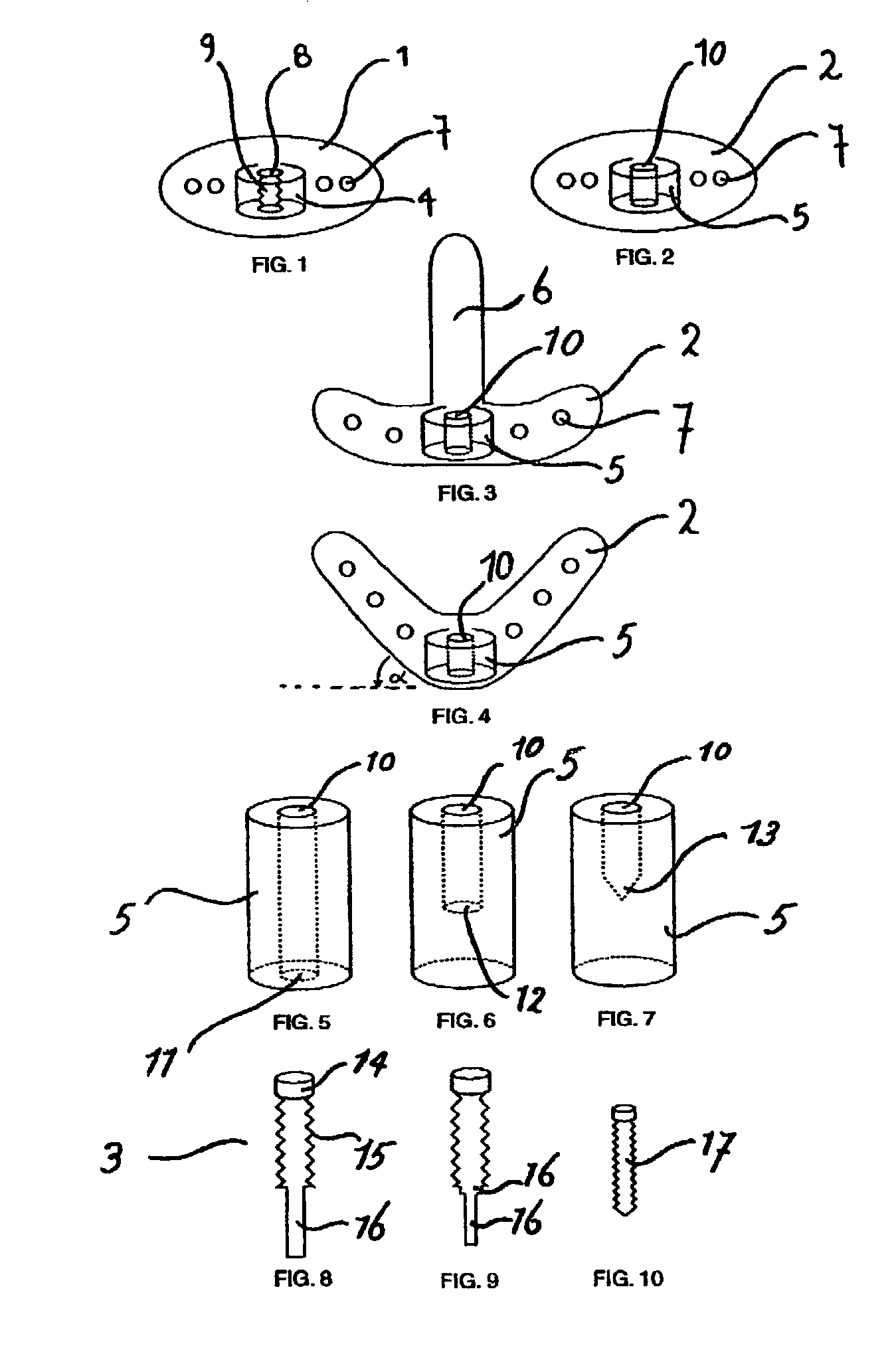
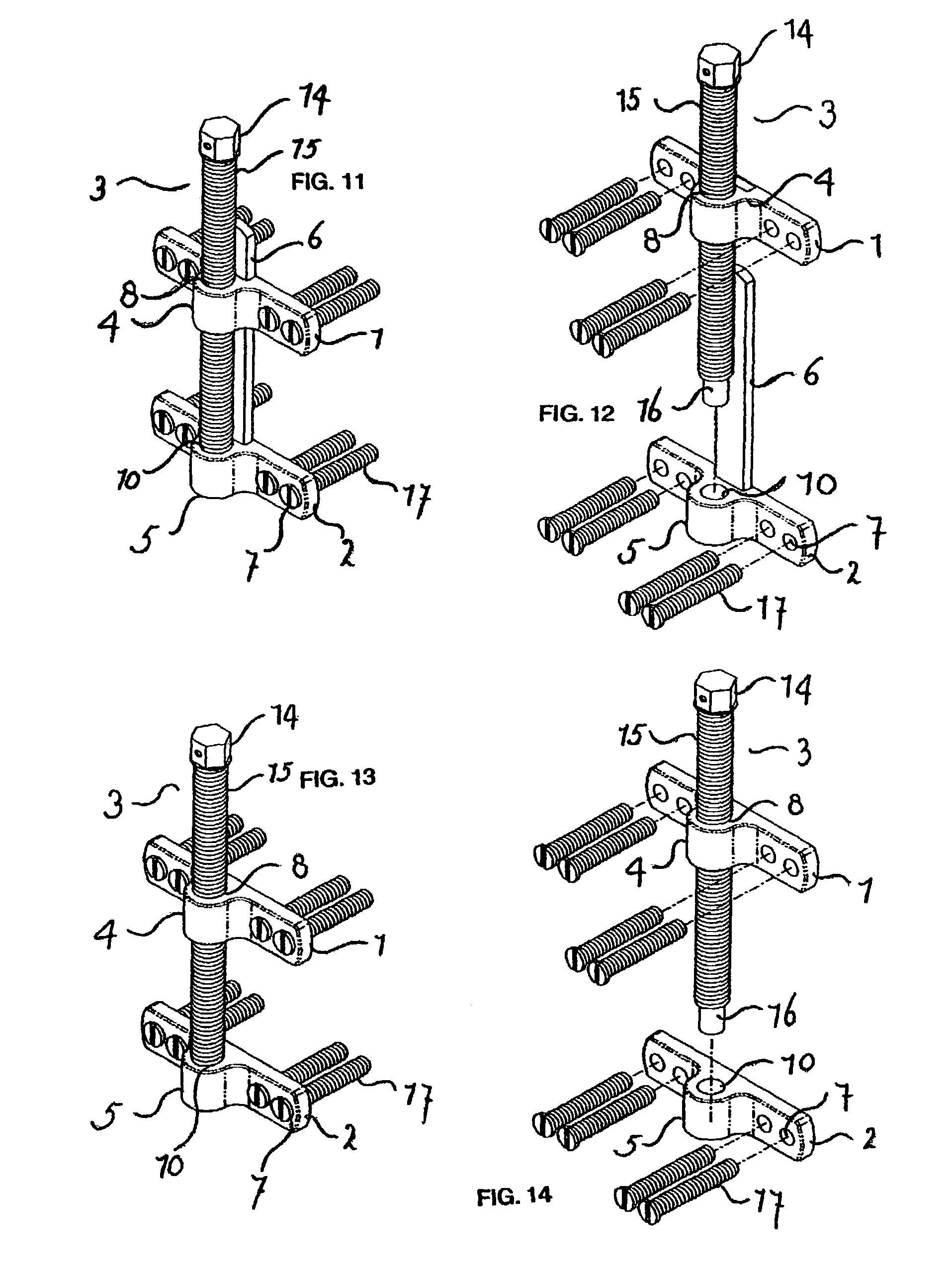
[0099]A device was manufactured with the following characteristics. The translating bracket comprises a cylinder, 2 perforations and 2 pins that match the perforations. The cylinder has an internal thread. The cylinder is located centrally (viewed in the frontal plane) of and anteriorly (viewed in the sagittal plane) to the translating bracket. The length of the cylinder runs perpendicularly to the plane of the bracket and perpendicularly to the plane of the distraction screw. The inner diameter of the cylinder is 2.0 mm, the thickness of the cylinder wall is 1.5 mm and the height of the cylinder is 3.0 mm.

[0100]The translating bracket comprises 2 perforations. The perforations are positioned in the horizontal to (viewed in a sagittal or transversal plane) the translating bracket, and are completely embedded in the bracket. The perforations are round, smooth and not internally threaded. The perforations match the diameter of the lateral pins and have a diameter of 0.9 mm. The perfor...

example 2

[0119]A second device is manufactured. This device is the same as the first device, but without the guiding rail. Again the device distracted a piece of the model for 20 mm.

example 3

[0120]A third device was manufactured. This device is half the size of the second device, apart from the length of the distraction screw, which was also 20 mm Again the device distracted a piece (part) of the model for 20 mm. When distracted at a length of 20 mm, a device with guiding rail is more stable and shows less torque. A device without guiding rail shows neither distortion nor bending at digital pressure in a mandibular model. While absent in the mandibular model, in the patient's mouth the periosteum and musculo-mucosal envelope would give additional rigidity and buccal tension to the device, likely to prevent the aforementioned slight transverse movement at maximum distraction length of 20 mm. The device was successfully tested in vitro. The design of the device takes into consideration the (specific) anatomical dimensions of the resorbed and atrophied mandible.


PUM


Abstract

The invention relates to a device that maybe used in maxillofacial surgery and dentistry. The device comprises a translating bracket with a cylinder and a fixed bracket with a chamber. A distraction screw is mounted through the cylinder and with one end resting on the chamber. By turning this screw when the device has been mounted on bone pieces osteogenesis can be achieved. The device can be made suitable for both dentulous and edentulous patients with alveolar defects.

Description

BACKGROUND OF THE INVENTION[0001]Distraction Osteogenesis has been used in the facial skeleton following the principles laid down by Codvilla in 1905 and Ilizarov in 1952. McCarthy first introduced distraction osteogenesis in the mandible (lower jaw). Several distraction devices have been disclosed in the art.[0002]McCarthy discloses in “Distraction of the craniofacial skeleton” (Springer Verlag, pages 68, 88, and 89; 1999) three extra-oral horizontal uniplanar and multiplanar distractors. The uniplanar distractors have two pin clamps, a distraction screw, and four percutaneous pins. The pins are of fixed length and about 80 mm long of which about 20 mm is fixed into the bone and 60 mm extends out of the bone. The diameter of the pin is between 10–15 mm in diameter. The distractor is placed percutaneously (through the skin of the face). The device is large, has a complex screw, and requires fixation through the skin with long pins. Therefore, fixation and removal needs to be perform...

Claims


Application Information

Patent Timeline
Patent Type & Authority Patents(United States)
IPC IPC(8): A61F5/04A61B17/66
CPCA61B17/663
Inventor WOLGEN, PHILIPPE
Owner FACEWORKS SOLUTIONS & TECH
Learn More