FCC reactor

Inactive Publication Date: 2007-07-31
SHELL OIL CO
View PDF10 Cites 11 Cited by
  • Summary
  • Abstract
  • Description
  • Claims
  • Application Information

AI Technical Summary

Benefits of technology

[0006]The object of the present invention is to provide a reactor in which the separation efficiency of the cyclone separation is less negatively affected by level fluctuations in the reactor vessel.

Problems solved by technology

A disadvantage of this reactor is that the separation in the primary cyclone can be negatively influenced when level fluctuations may for example be caused by pressure fluctuations in the system, by standpipe-instabilities or slide-valve problems.

Method used


Image

  • FCC reactor
  • FCC reactor
  • FCC reactor

Examples


Embodiment Construction

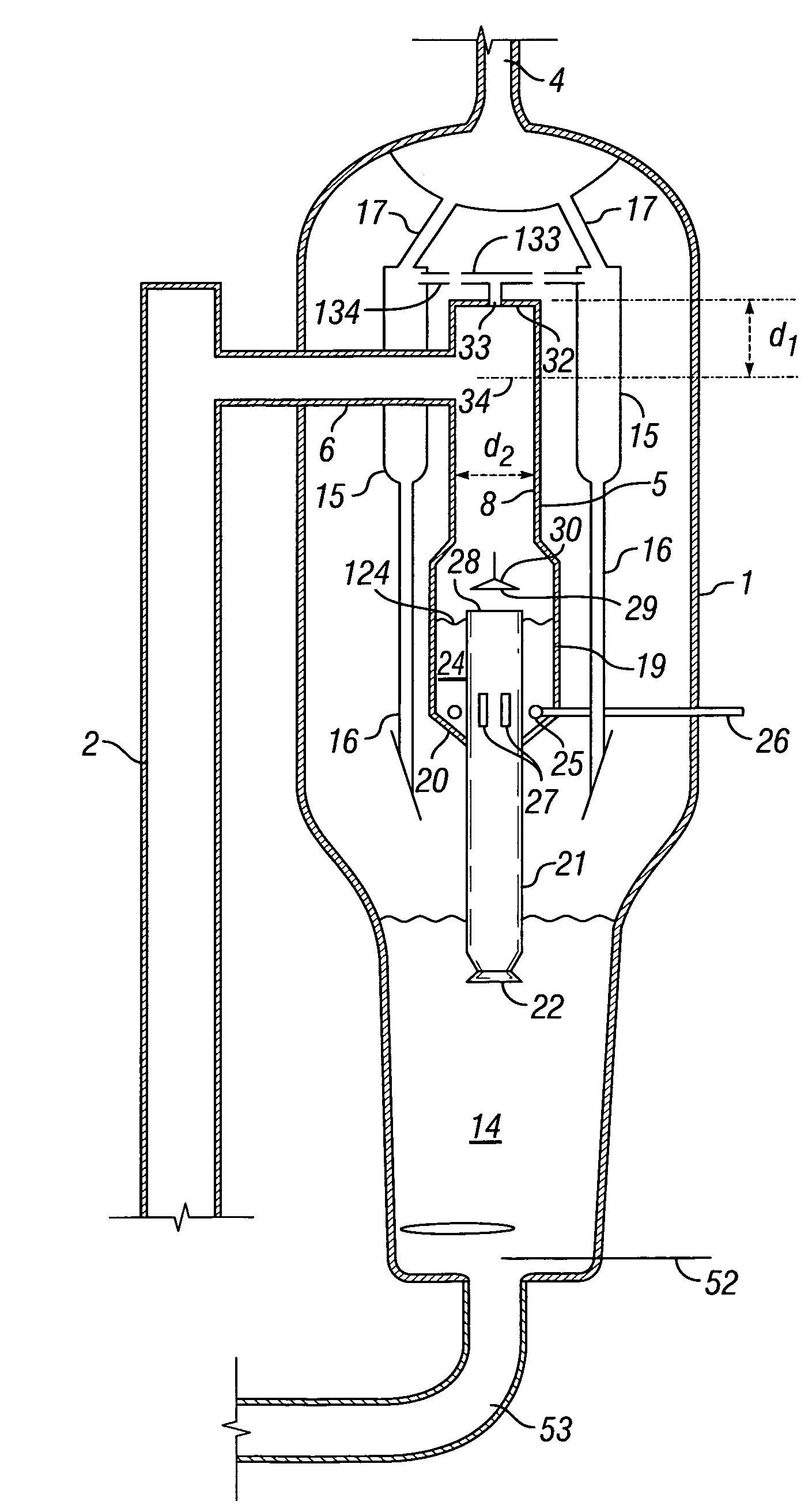
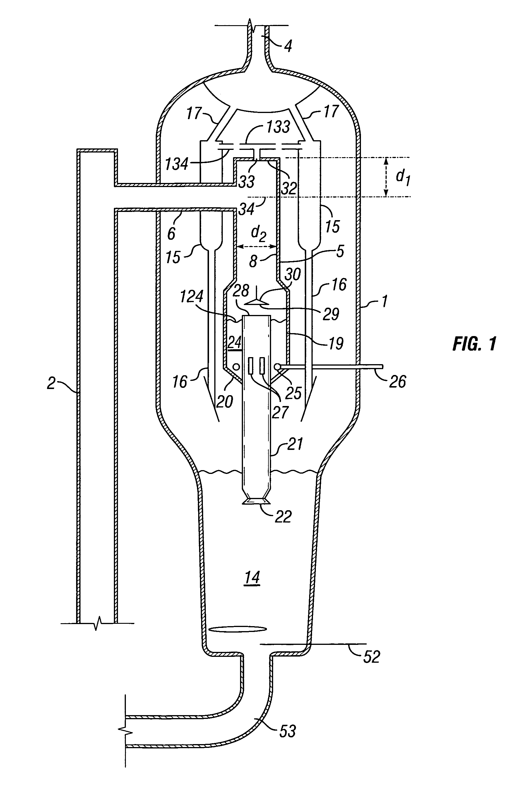
[0014]Applicant found that the overall stripping efficiency as achieved in the reactor vessel according to the invention is enhanced. Because stripping takes place in two physically separate zones more staging and therefore a higher efficiency is achieved. This stripping efficiency is further improved when in the separate stripping zones a near counter-current contacting of catalyst and stripping gas is achieved. Preferred embodiments of the invention as shown below are especially directed to achieve just such an effect.

[0015]Furthermore, because the interior of the primary cyclone comprising the primary stripping zone is not in direct open communication with the reactor interior of the reactor vessel as for example in the reactor disclosed in U.S. Pat. No. 5,869,008, level fluctuations in said vessel do not negatively influence the separation efficiency of the cyclone as compared to the prior art design.

[0016]The design is furthermore advantageous because more space is present with...


PUM

PropertyMeasurementUnit
Diameteraaaaaaaaaa

Abstract

A fluid catalytic reactor vessel having at its upper end a single centrally positioned primary cyclone having a gas-solids inlet fluidly connected to the downstream end of a fluid catalytic riser, which riser is positioned externally from a fluid catalytic reactor vessel. The primary cyclone is further provided with a gas outlet conduit at its upper end fluidly connected to one or more secondary cyclone separators, which secondary cyclone separators are positioned in the space between the centrally positioned primary cyclone and the wall of the reactor vessel and which secondary cyclones have means to discharge solids to the lower end of the reactor vessel and means to discharge a gaseous stream poor in solids to a gas outlet of the reactor vessel. The primary cyclone is further provided with a primary stripping zone at its lower end and means to discharge pre-stripped solids from the primary cyclone to the lower end of the reactor vessel. The reactor vessel further comprises at the lower end of reactor vessel a secondary stripping zone is and means to discharge stripped solids from the reactor vessel.

Description

FIELD OF THE INVENTION[0001]The invention is related to Fluid catalytic reactor vessel comprising:[0002]at its upper end a single centrally positioned primary cyclone having a gas-solids inlet fluidly connected to the downstream end of a fluid catalytic riser, which riser is positioned externally from the fluid catalytic reactor vessel;[0003]said primary cyclone further provided with a gas outlet conduit at its upper end fluidly connected to one or more secondary cyclone separators, which secondary cyclone separators are positioned in the space between the centrally positioned primary cyclone and the wall of the reactor vessel and which secondary cyclones have means to discharge solids to the lower end of the reactor vessel and means to discharge a gaseous stream poor in solids to a gas outlet of the reactor vessel. The lower end of the vessel is furthermore provided with a stripping zone.BACKGROUND OF THE INVENTION[0004]Such a reactor is described in U.S. Pat. No. 5,449,498. Accord...

Claims


Application Information

Patent Timeline
IPC IPC(8): B32B5/02B01J8/00B01J8/18B04C5/26C10G11/18
CPCB01J8/0055B01J8/18B04C5/26C10G11/18B01J2208/00761
Inventor CHEN, YE-MONDEWITZ, THOMAS SHAWNDIRKSE, HENDRICUS ARIENDRIES, HUBERTUS WILHELMUS ALBERTUSSANBORN, RICHARD ADDISON
Owner SHELL OIL CO
Why Eureka
Try Eureka